

Device for centering and guiding a drill bit of a dental handpiece
Patent Information
- Authority / Receiving Office
- US · United States
- Current Assignee / Owner
- Publication Date
- 2010-12-09
Smart Images
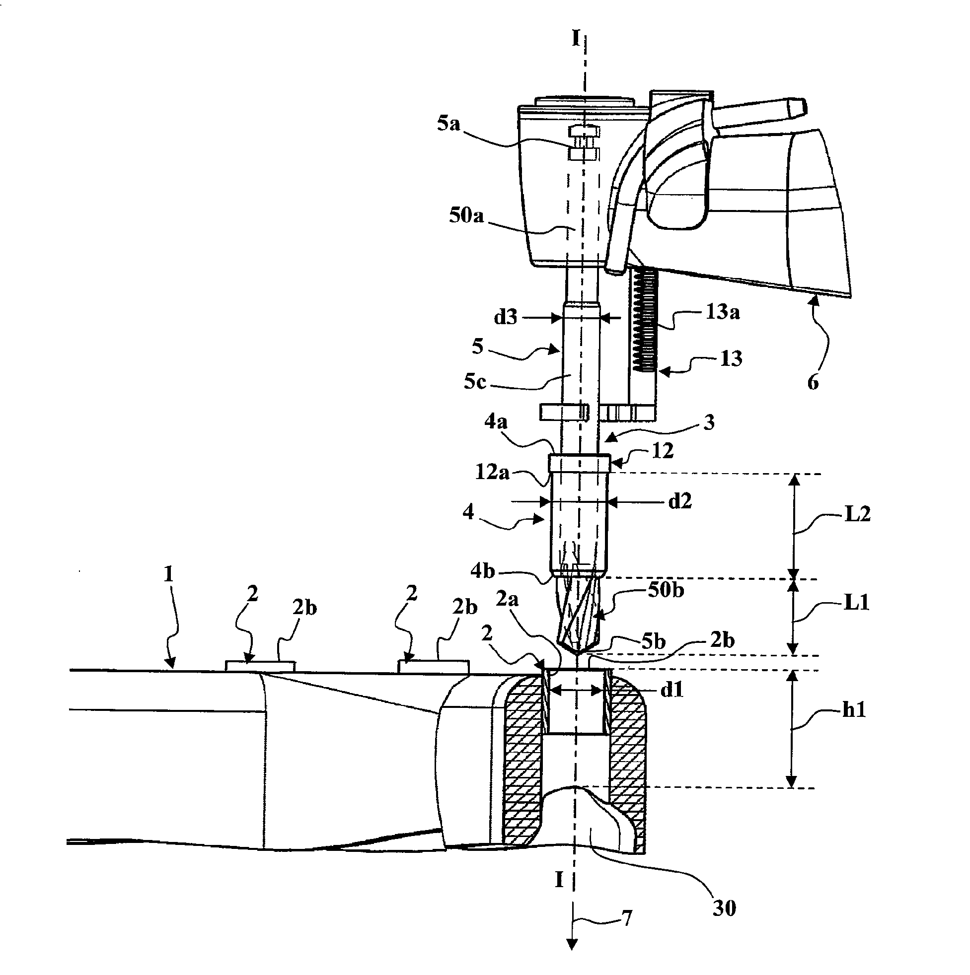
Figure 1 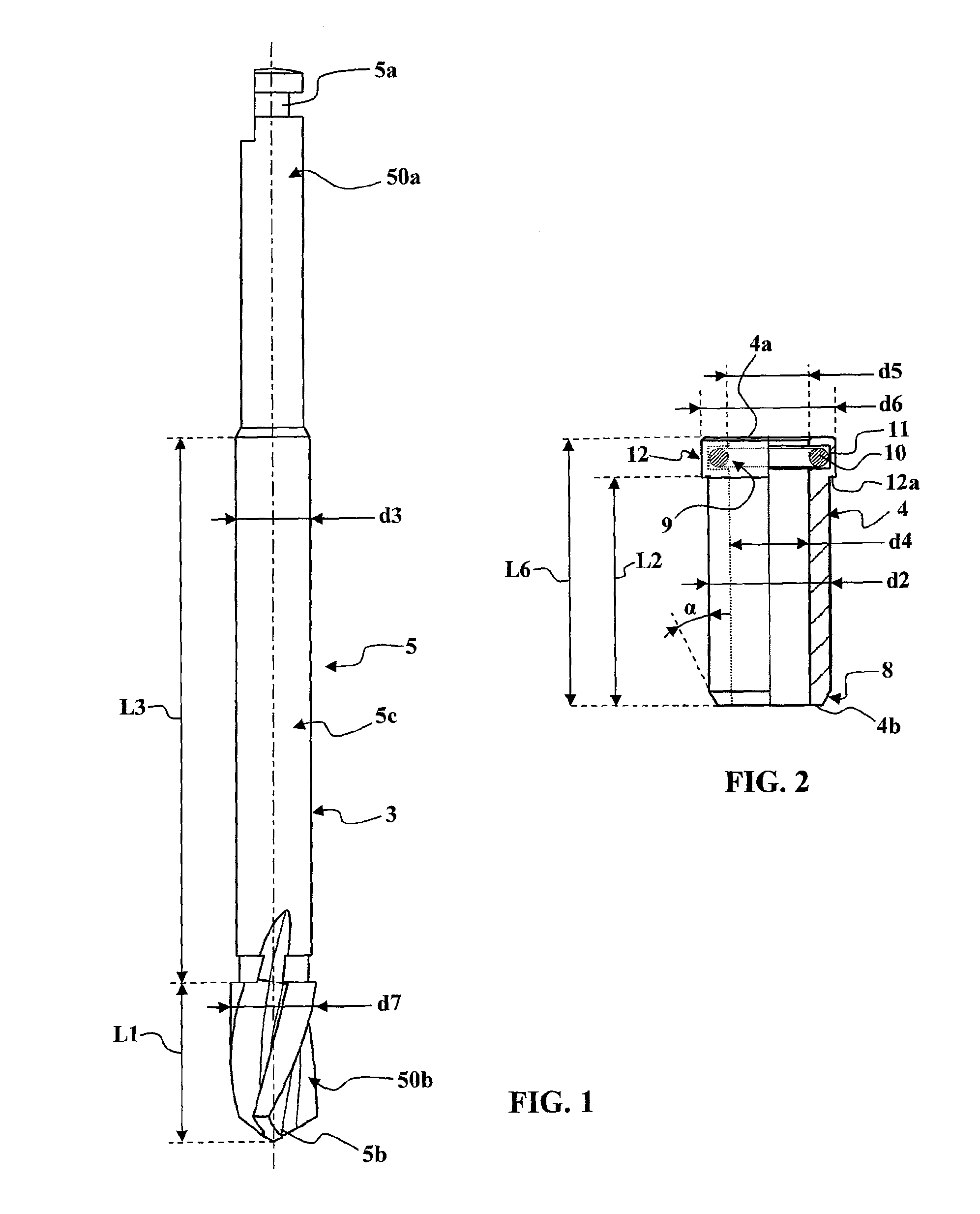
Figure 2 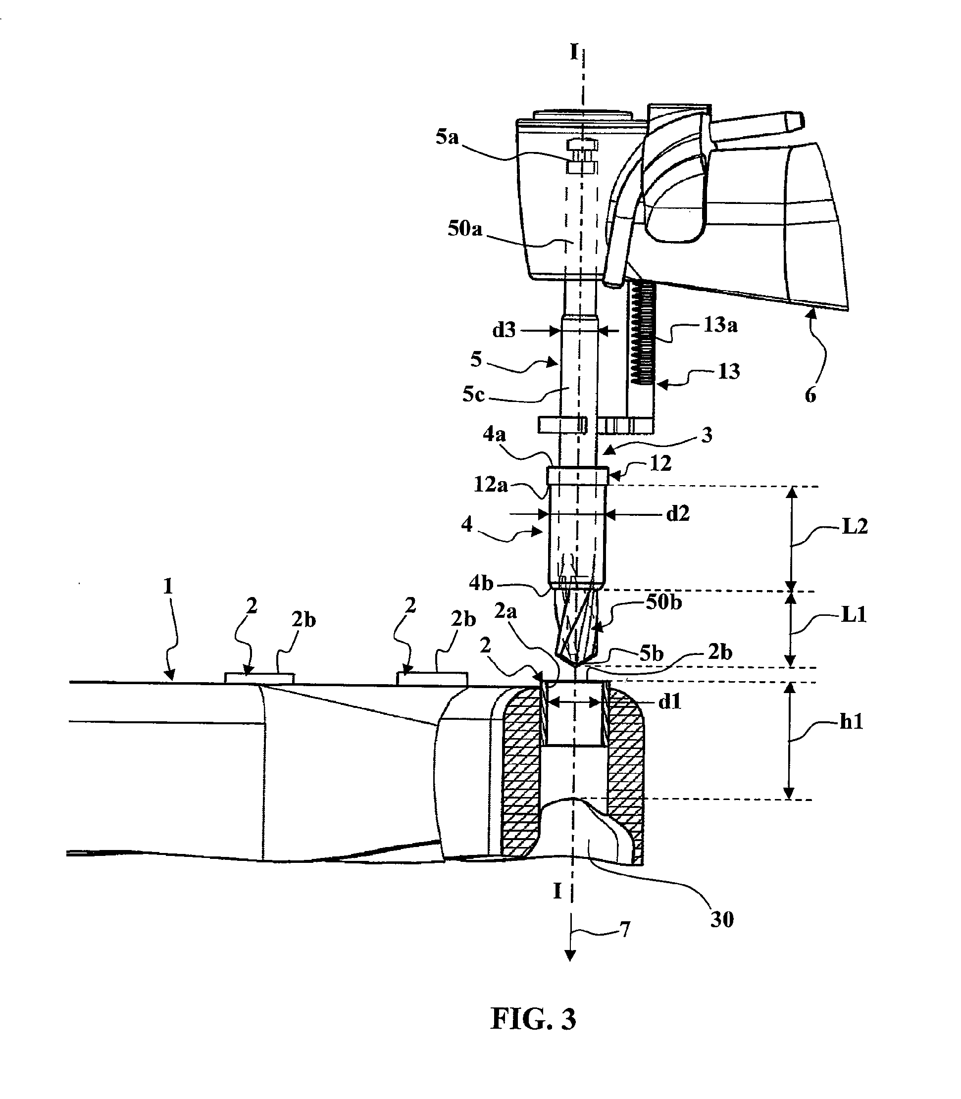
Figure 3
Abstract
Description
TECHNICAL FIELD OF THE INVENTION
[0001] The present invention concerns dental implants and more particularly installing dental implants assisted by a surgical guide placed in the mouth of the patient.
[0002] To replace damaged teeth in the mouth of a patient, implants fixed into the jawbone of the patient have been used for many years. After drilling a hole in the jawbone of the patient using a dental handpiece, the proximal part of an implant is screwed into the hole after which its distal part receives a dental prosthesis.
[0003] To assist the practitioner to produce the holes in the jawbone of the patient, surgical guides have been used for a number of years that the practitioner can fit in the patient's mouth on their jaw. This kind of surgical guide is an arcuate structure that follows the curvature of the jaw and that is provided with one or more tubular drilling bushes that extend as far as the vicinity of the area of the jawbone to be drilled. These surgical guides are produced us...
Examples
example 1
Drilling a Hole in the Jaw of the Patient with a Device of the First Embodiment
[0119]In this example, the following choices are made:
[0120]h1 is made equal to 9 mm,
[0121]L1 is made equal to 5 mm,
[0122]L2 is made equal to 8 mm,
[0123]L3 is made equal to 30 mm,
[0124]L6 is made equal to approximately 10 mm,
[0125]d1 is made equal to 4.2 mm,
[0126]d2 is made equal to 4.17 mm,
[0127]d3 is made equal to 2.8 mm;
[0128]d4 is made equal to 2.8 mm (+clearance),
[0129]d5 is made equal to 2.8 mm (+clearance),
[0130]d6 is made equal to 4.6 mm.
[0131]The practitioner mounts the guide sleeve 4 on the intermediate section 5c with the distal end 4b abutted against the distal cutting section 50b and then fixes the drill bit 5 to the dental handpiece 6 fitted with abutment means 13. The practitioner then adjusts the height of the abutment means 13 to drill a hole of particular depth.
[0132]When the drill bit 5 comes into contact with the jawbone of the patient, the guide sleeve 4 is already engaged in the tubu...
example 2
Adjustment of the Device of the Second Embodiment to Drill a Hole 8 Mm Deep in the Jaw of the Patient
[0159]In this example, the first height h1 is 9 mm, the axial movement allowed by the spring means 15 is 15 mm and the axial length L5 of the guide sleeve 4 is 8 mm.
[0160]To adjust conveniently the axial position of the guide sleeve 4, the practitioner mounts the drill bit 5 and the centering and guiding device of the second embodiment of the invention on the dental handpiece 6.
[0161]The rack of the support rod 19 is immobilized in the receiving sleeve 20 so that, when the spring means 15 are compressed (guide sleeve 4 in high position), the proximal end 4a of the guide sleeve is at a distance from the distal end 5b of the drill bit 5 equal to the sum of the first height h1 and the required depth of the hole (8 mm in this example), that is to say 17 mm here. In the low position, the proximal end 4a of the guide sleeve 4 is therefore offset from the distal end 5b of the drill bit 5 by...
example 3
Adjustment of the Device of the Second Embodiment to Drill a Hole 15 Mm Deep in the Jaw of the Patient
[0162]In this example, the first height h1 is 9 mm, the axial movement allowed by the spring means 15 is 15 mm and the axial length L5 of the guide sleeve 4 is 8 mm.
[0163]In order to adjust conveniently the axial position of the guide sleeve 4, the practitioner mounts the drill bit 5 and the centering and guiding device of the second embodiment of the invention on the dental handpiece 6. The rack of the support rod 19 is immobilized in the receiving sleeve 20 so that, when the spring means 15 are compressed (guide sleeve 4 in high position), the proximal end 4a of the guide sleeve is at a distance from the distal end 5b of the drill bit 5 equal to the sum of the first height h1 and the required depth of the hole (15 mm in this example), i.e. 24 mm here.
[0164]In the low position, the proximal end 4a of the guide sleeve 4 is therefore offset from the distal end 5b of the drill bit 5 b...