
Electrical push device
a push device and push technology, applied in the direction of electrical equipment, dynamo-electric machines, gearing, etc., can solve the problems of large power consumption, many malfunctions, and drawbacks of high temperature rise and many malfunctions, so as to reduce malfunctions, reduce operating temperature rise, and save power
Patent Information
- Authority / Receiving Office
- US · United States
- Patent Type
- Applications(United States)
- Current Assignee / Owner
- Publication Date
- 2012-04-26
- Estimated Expiration
- Not applicable · inactive patent
Smart Images
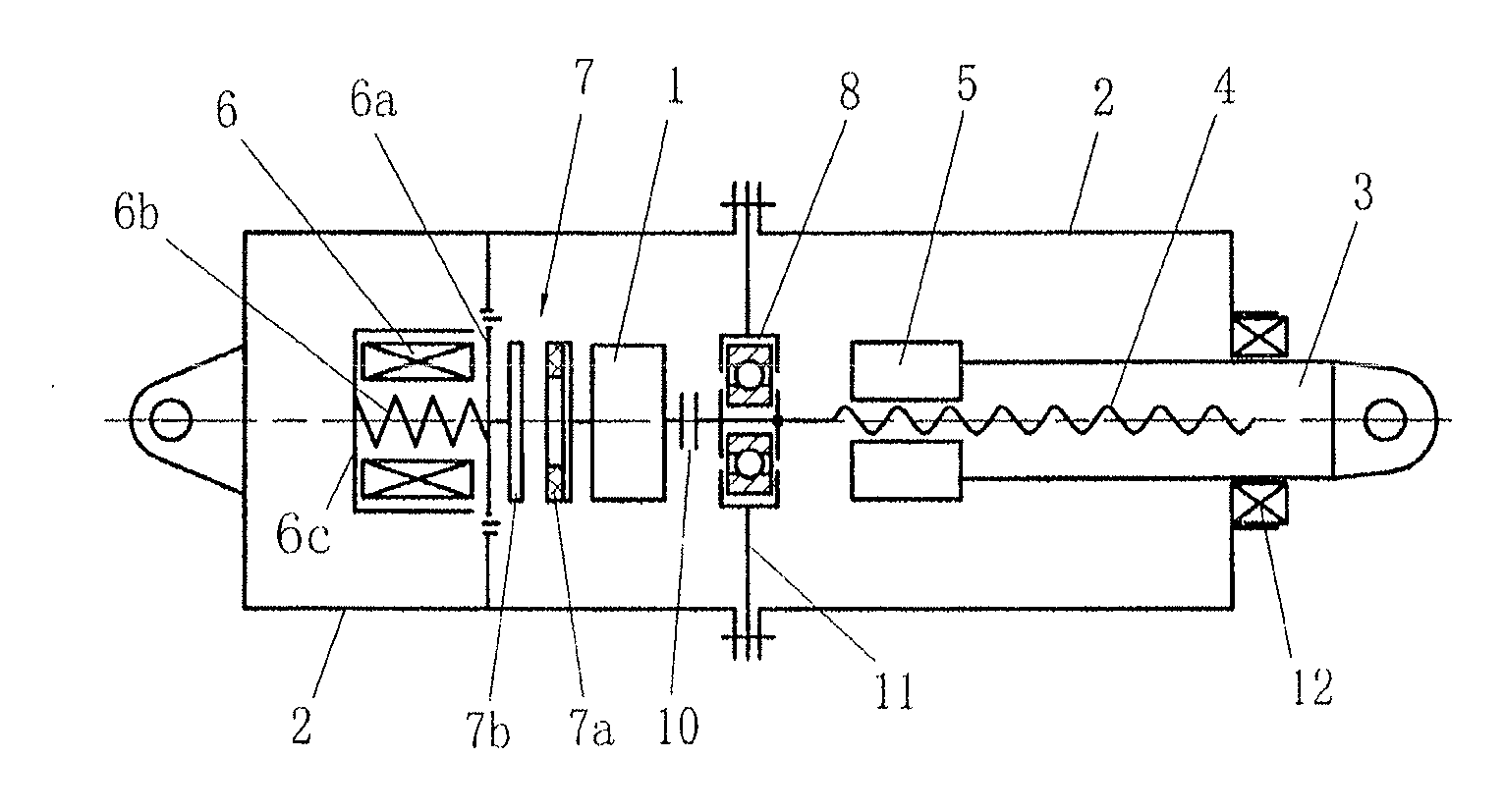
Figure 1 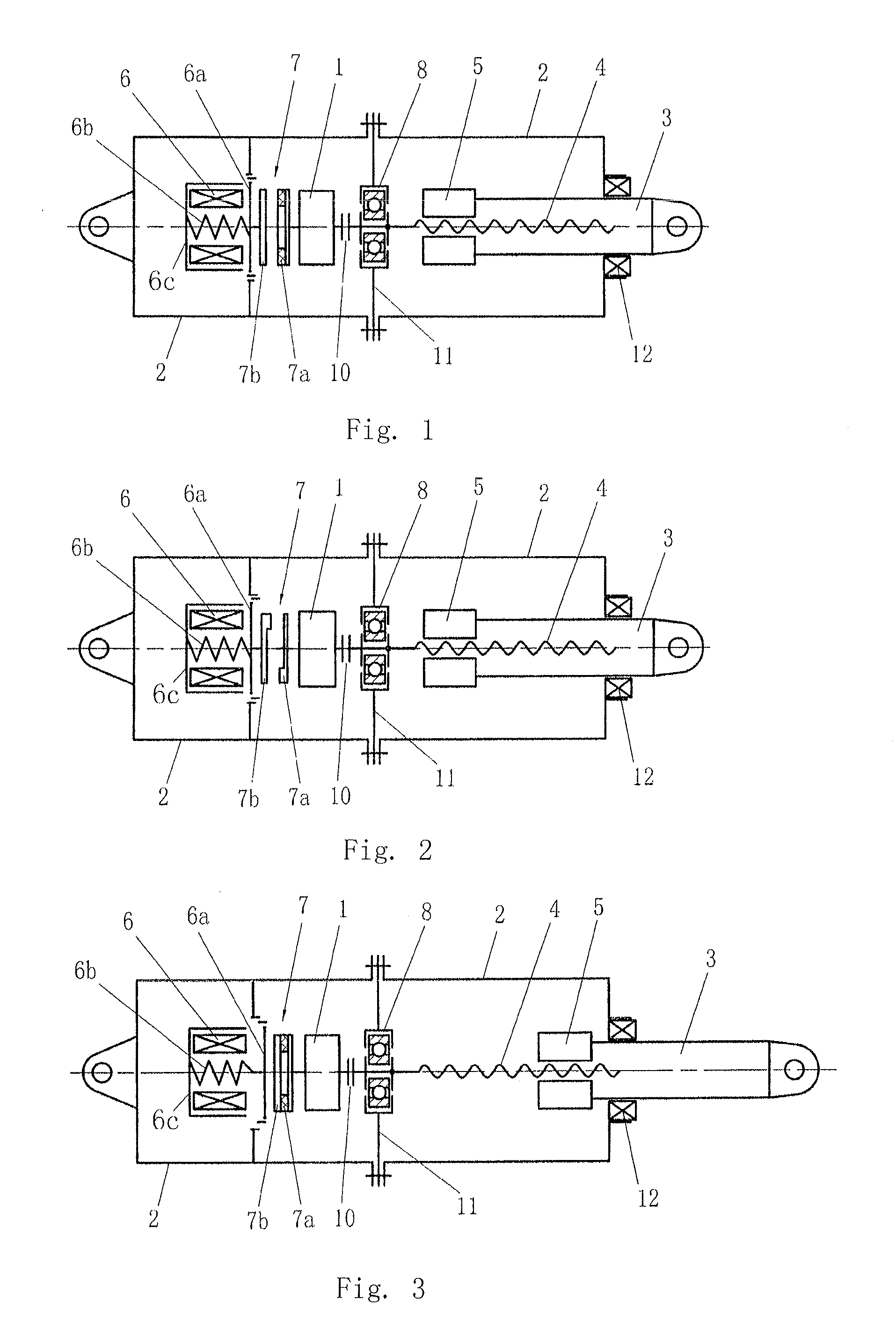
Figure 2 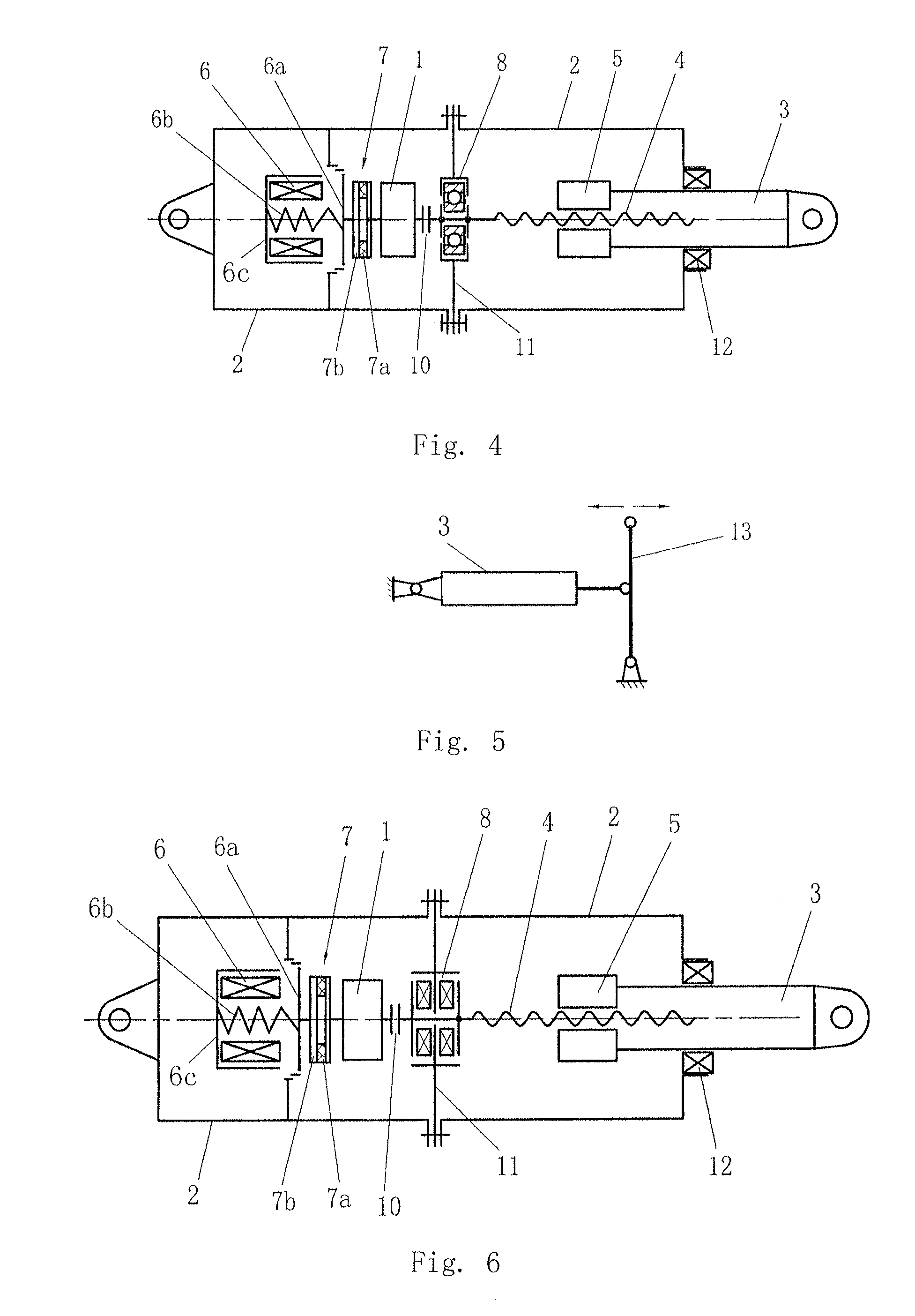
Figure 3
Abstract
Description
FIELD OF THE INVENTION
[0001] The present invention relates to a device for pushing a member or a mechanism to move, and in particular, to an electrical push device.DESCRIPTION OF THE RELATED ART
[0002] Patent Document CN2847660Y published on Dec. 13, 2006 discloses “a novel electrical push rod”. The electrical push rod for an arrester, comprises a motor, an upper stroke switch, a down stroke switch, and a housing. The motor is connected with the lower end of the housing. An outwardly movably push rod is provided in the upper part of the housing, and a spring seat is provided in the lower part. The output shaft of the motor is connected with a lead screw. The inner end of the lead screw and the spring seat constitute a screw pair. The upper segment of the lead screw is provided with a compression spring acting on the push rod. The working process is operated as follows: the motor is rotated to drive the lead screw to rotate, through the screw pair function constituted by the lower part ...
Examples
first embodiment
[0030]The first embodiment is shown in FIG. 1.
[0031]Referring to FIG. 1, according to the present invention, an electrical push device comprises a motor 1, a housing 2, an axially movable push rod 3 provided in the housing 2, a lead screw 4 provided in the push rod 3, and, a screw nut 5 provided in the inner end of the push rod 3, the screw nut 5 and the lead screw 4 constituting a screw pair. The screw nut 5 and the lead screw 4 may preferably adopt a ball lead screw and ball screw nut structure, although it is not limited to this according to the present invention, and any other suitable types of the screw pair my be adopted. The helix rise angle of the lead screw 4 which is engaged with the screw nut 5 is larger than the locking angle. The inner segment of the lead screw 4 is provided with a supporting bearing 8. The supporting bearing 8 is connected to the housing 2 through a member 11. The inner end of the lead screw 4 is connected with the shaft of the motor 1. Specifically, i...
second embodiment
[0033]The second embodiment is shown in FIG. 2.
[0034]Referring to FIG. 2, the present embodiment has a modified structure of the brake pair 7, based on the first embodiment. The translational movement brake disc 7b and the rotating brake disc 7a of the brake pair 7 shown in FIG. 1 have the annular engaging faces, however, the translational movement brake disc 7b and the rotating brake disc 7a of the brake pair 7 in the present embodiment have boss-type engaging faces, but the rest of the present embodiment is as the same as that of the first embodiment. Specifically, based on the embodiment shown in FIG. 1, a portion of the brake friction surface of the rotating brake disc 7a is provided on the translational movement brake disc 7b , so as to form a boss-type structure.
third embodiment
[0035]The third embodiment is shown in FIG. 3.
[0036]The technical solution of the present embodiment is different from that of the first embodiment in that: the initial position of the screw nut 5 on the push rod 3 is located in the outer end part of the lead screw 4. When the motor 1 is electrically driven to operate, the push rod 3 along with the screw nut 5 inwardly moves along the lead screw 4, correspondingly to draw the push rod 3 back, that is, to draw the member or mechanism connected with the push rod. When the electromagnet 6 is in an electrically driven condition, as shown in FIG. 1, the translational movement brake disc 7b and the rotating brake disc 7a are in an engagement state to maintain the push rod 3 in the state of being at the outer end part of the lead screw 4 by the brake force produced from the engagement between the translational movement brake disc 7b and the rotating brake disc 7a. The rest of the present embodiment is as the same as that of the first embod...