
Turbine
a technology of internal combustion engine and turbine, which is applied in the direction of machines/engines, stators, liquid fuel engines, etc., can solve the problems of reduced gas entering the impeller gas feeding passage from the impeller gas inlet, low efficiency of the turbine, etc., and achieves excellent succession, high casting yield, and simple structure.
Patent Information
- Authority / Receiving Office
- US · United States
- Current Assignee / Owner
- Publication Date
- 2015-03-05
- Estimated Expiration
- Not applicable · inactive patent
Smart Images
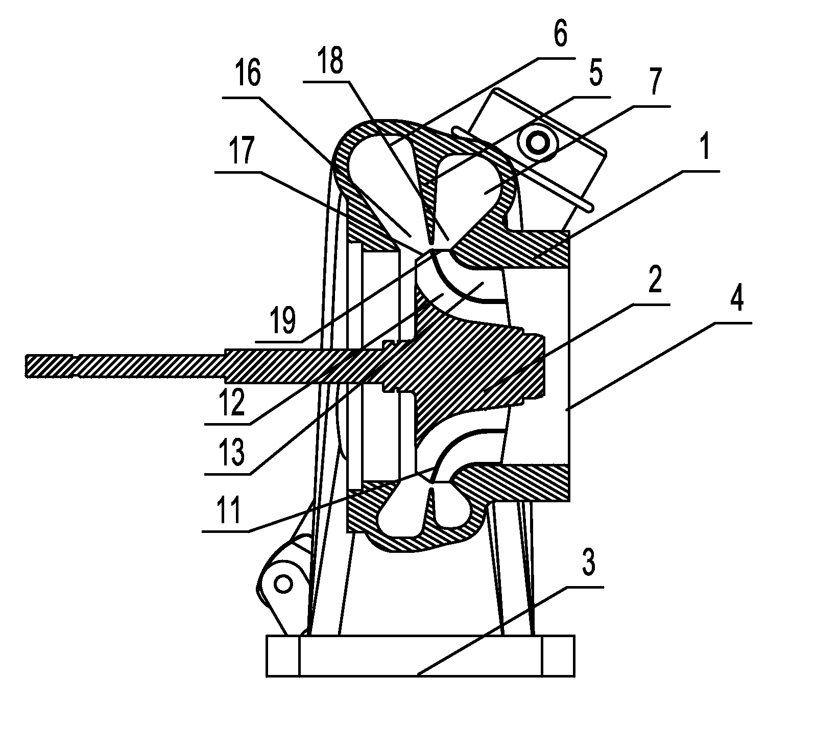
Figure 1 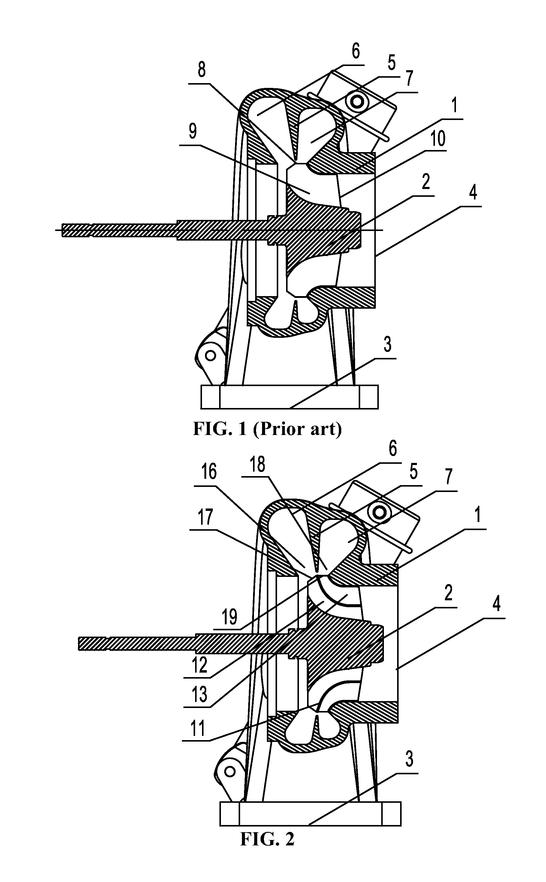
Figure 2 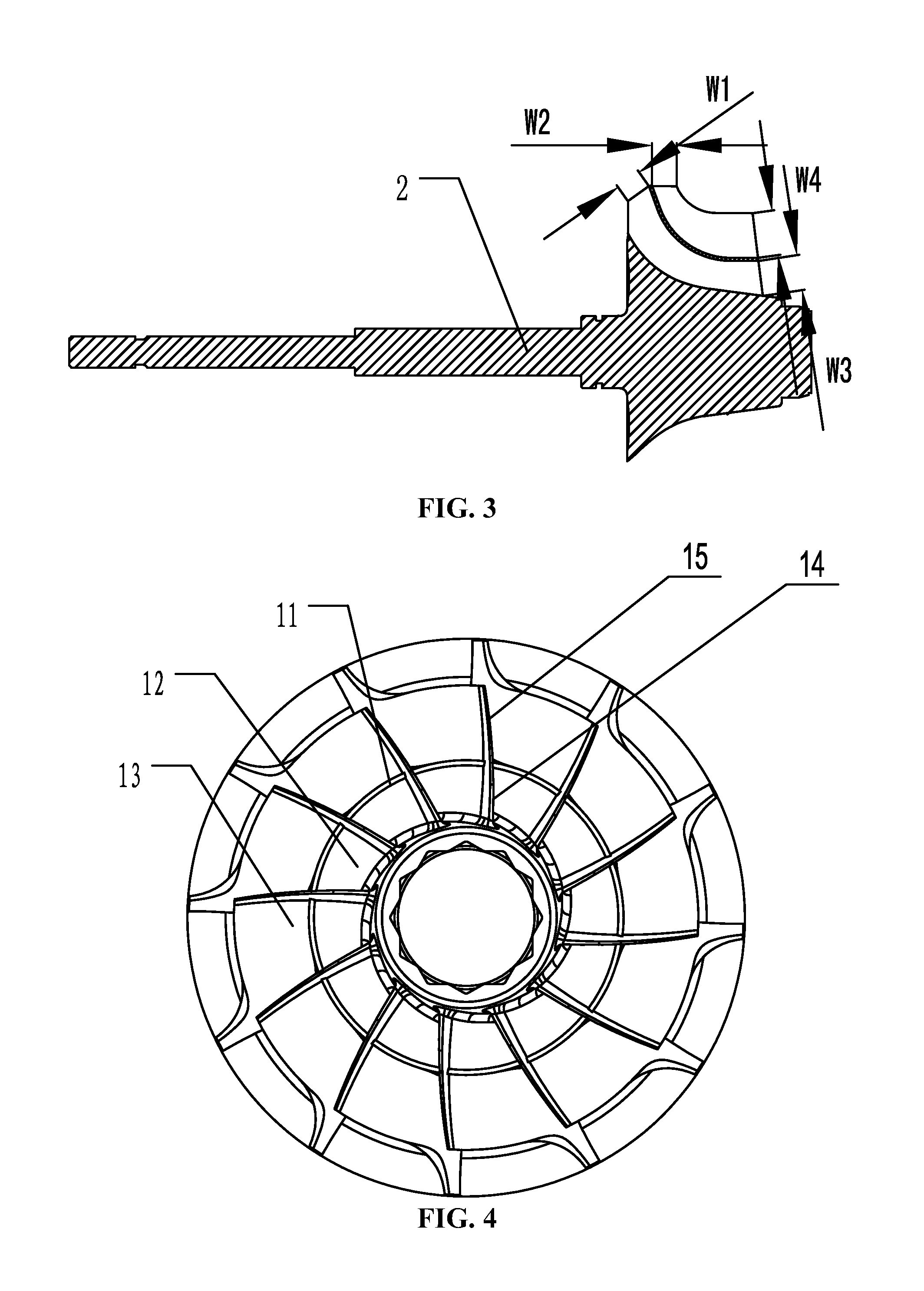
Figure 3
Abstract
Description
CROSS-REFERENCE TO RELATED APPLICATIONS
[0001] This application is a continuation-in-part of International Patent Application No. PCT / CN2012 / 000714 with an international filing date of May 22, 2012, designating the United States, now pending, and further claims priority benefits to Chinese Patent Application No. 201210137082.5 filed May 7, 2012. The contents of all of the aforementioned applications, including any intervening amendments thereto, are incorporated herein by reference. Inquiries from the public to applicants or assignees concerning this document or the related applications should be directed to: Matthias Scholl P.C., Attn.: Dr. Matthias Scholl Esq., 245 First Street, 18th Floor, Cambridge, Mass. 02142.BACKGROUND OF THE INVENTION
[0002] 1. Field of the Invention
[0003] The invention relates to the field of turbocharging of an internal combustion engine, and more particularly to a turbine.
[0004] 2. Description of the Related Art
[0005] A typical double-layer flow passage cross-se...
Examples
example 1
[0038]As shown in FIGS. 2-3, a double-area turbine for turbocharging comprises a volute 1 and an impeller 2 disposed inside the volute 1. Blades are disposed at an outer part of the impeller 2. The volute 1 comprises: a volute gas inlet 3, a volute gas feeding flow passage, and a volute gas outlet 4.
[0039]The impeller 2 comprises: an impeller gas inlet, an impeller gas feeding flow passage, an impeller gas outlet, and blades.
[0040]A partition plate 11 is circumferentially disposed between the impeller gas inlet and the impeller gas outlet. The shape of the partition plate 11 satisfies aerodynamic performance requirements and reliability requirements.
[0041]The partition plate 11 divides the impeller gas feeding flow passage into an inner flow passage 12 and an outer flow passage 13.
[0042]The inner flow passage 12 adopts a radial inflow channel or Francis channel. The outer flow passage 13 is generally designed to be a radial inflow channel and is designed to be a Francis channel in s...
example 2
[0052]As shown in FIG. 6, the turbine of this example is different from that in Example 1 in that the adjustable valve 20 herein is disposed inside the right flow passage 7 in the vicinity of the volute gas inlet 3 rather than being disposed inside the left flow passage 6 in the vicinity of the volute gas inlet 3 in Example 1. The adjustable valve 20 is connected to a control mechanism. The rotation of the adjustable valve 20 can be realized driven by the control mechanism, so that the right flow passage 7 is opened or closed.
[0053]When the motor operates at the low rotational speed working condition, a relatively small amount of exhaust gas is discharged from the motor, and the adjustable valve 20 is in a close state driven by the control mechanism. Thus, the right flow passage 7, the gas inlet 19 of the outer flow passage, and the outer flow passage 13 are also in the close sate. The exhaust gas discharged from the motor only passes through the left flow passage 6, the gas inlet 1...