
Mixer assembly for a gas turbine engine
Patent Information
- Authority / Receiving Office
- US · United States
- Current Assignee / Owner
- Publication Date
- 2015-05-07
Smart Images
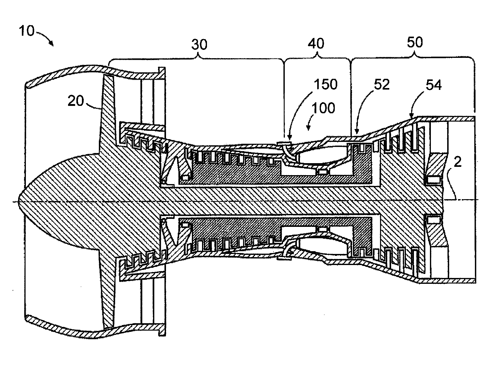
Figure 1 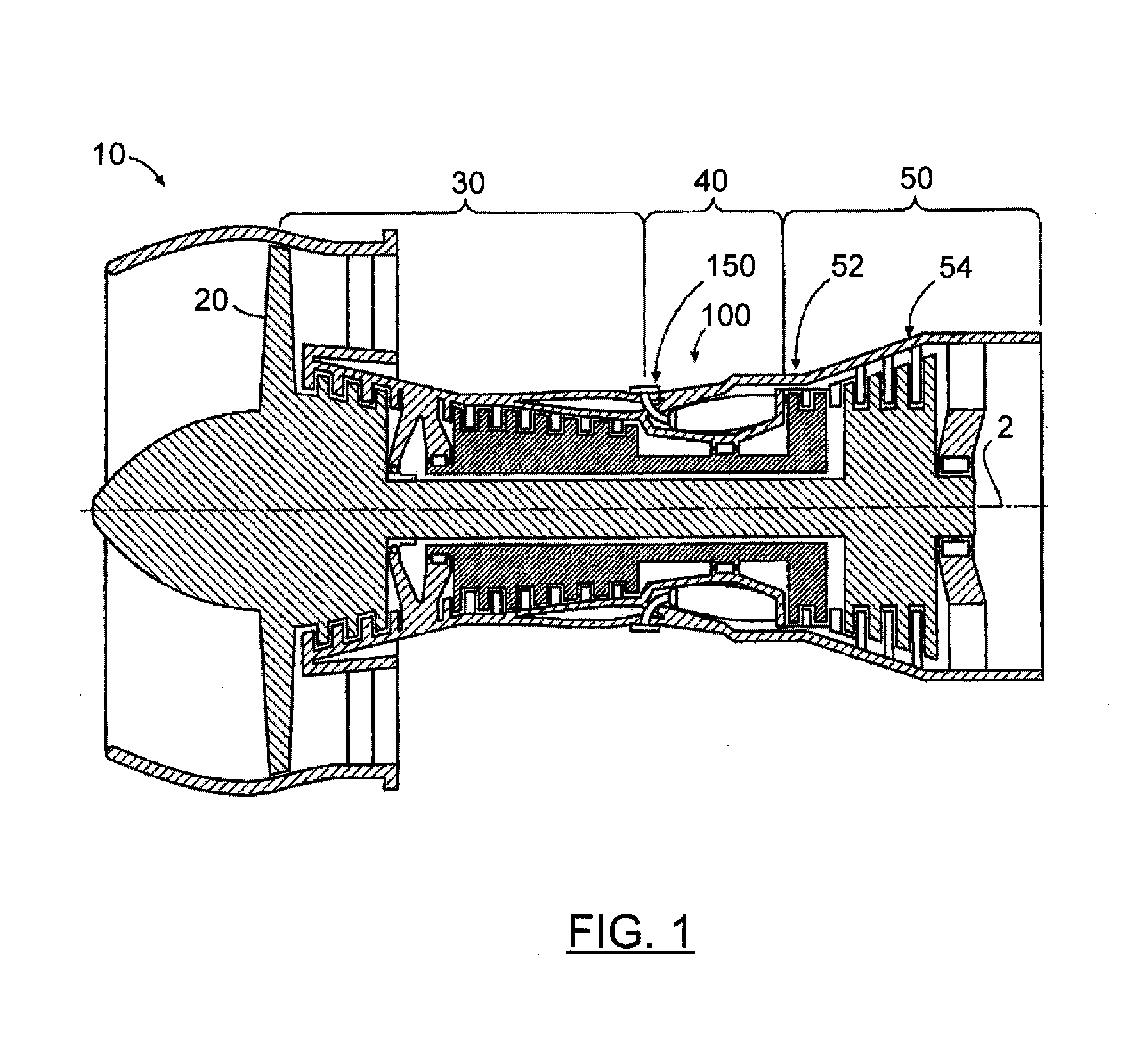
Figure 2 
Figure 3
Abstract
Description
CROSS-REFERENCE TO RELATED APPLICATIONS
[0001] This application is a continuation patent application under 35 USC §120 claiming priority to U.S. non-provisional patent application Ser. No. 13 / 014,388 filed on Jan. 26, 2011.STATEMENT OF FEDERALLY SPONSORED RESEARCH OR DEVELOPMENT
[0002] This invention was made with Government support under Contract No. NNC08CA92C awarded by the National Aeronautics and Space Administration (NASA). The U.S. Government has certain rights in the invention.FIELD OF THE DISCLOSURE
[0003] The subject matter disclosed herein relates generally to combustors for gas turbine engines and more particularly to mixer assemblies for gas turbine engines.BACKGROUND OF THE DISCLOSURE
[0004] Gas turbine engines, such as those used to power modern aircraft, to power sea vessels, to generate electrical power, and in industrial applications, include a compressor for pressurizing a supply of air, a combustor for burning a hydrocarbon fuel in the presence of the pressurized air, an...
Examples
Embodiment Construction
[0016]FIG. 1 is a schematic diagram of an exemplary embodiment of a gas turbine engine 10. The gas turbine engine 10 is depicted as a turbofan that incorporates a fan section 20, a compressor section 30, a combustion section 40, and a turbine section 50. The combustion section 40 incorporates a combustor 100 that includes a plurality of fuel injectors 150 that are positioned annularly about a centerline 2 of the engine 10 upstream of the turbines 52, 54. Throughout the application, the terms “forward” or “upstream” are used to refer to directions and positions located axially closer toward a fuel / air intake side of a combustion system than directions and positions referenced as “aft” or “downstream.” The fuel injectors 150 are inserted into and provide fuel to one or more combustion chambers for mixing and / or ignition. It is to be understood that the combustor 100 and fuel injector 150 as disclosed herein are not limited in application to the depicted embodiment of a gas turbine eng...