
Vehicle brushless ac generator
a brushless ac generator and ac generator technology, applied in the direction of electrical apparatus, dynamo-electric machines, structural associations, etc., can solve the problems of affecting the work efficiency of the connection bracket, so as to improve the workability and reduce the coil space factor in the slot , the effect of improving the outpu
Patent Information
- Authority / Receiving Office
- US · United States
- Patent Type
- Applications(United States)
- Current Assignee / Owner
- Publication Date
- 2015-06-18
Smart Images
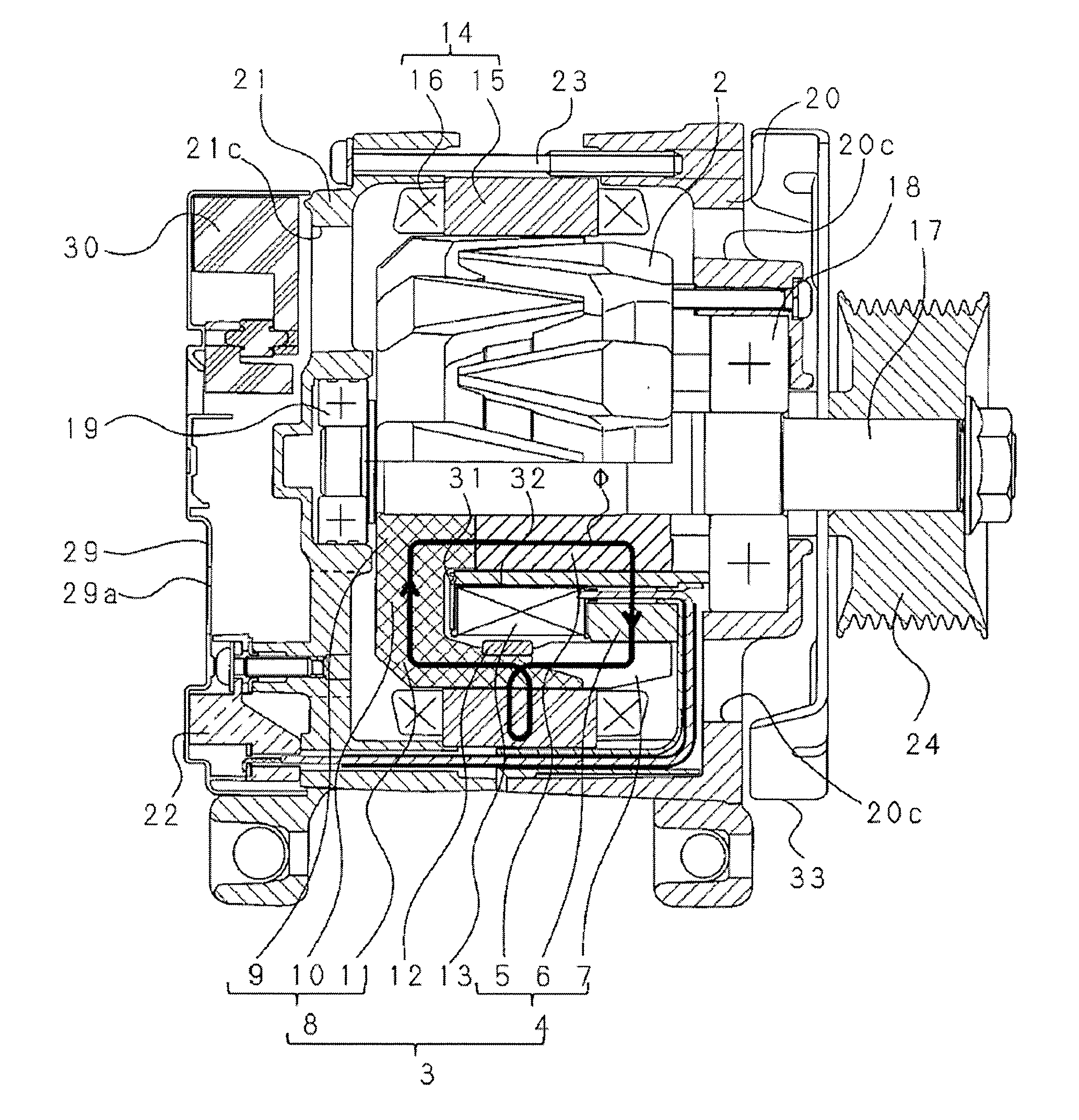
Figure 1 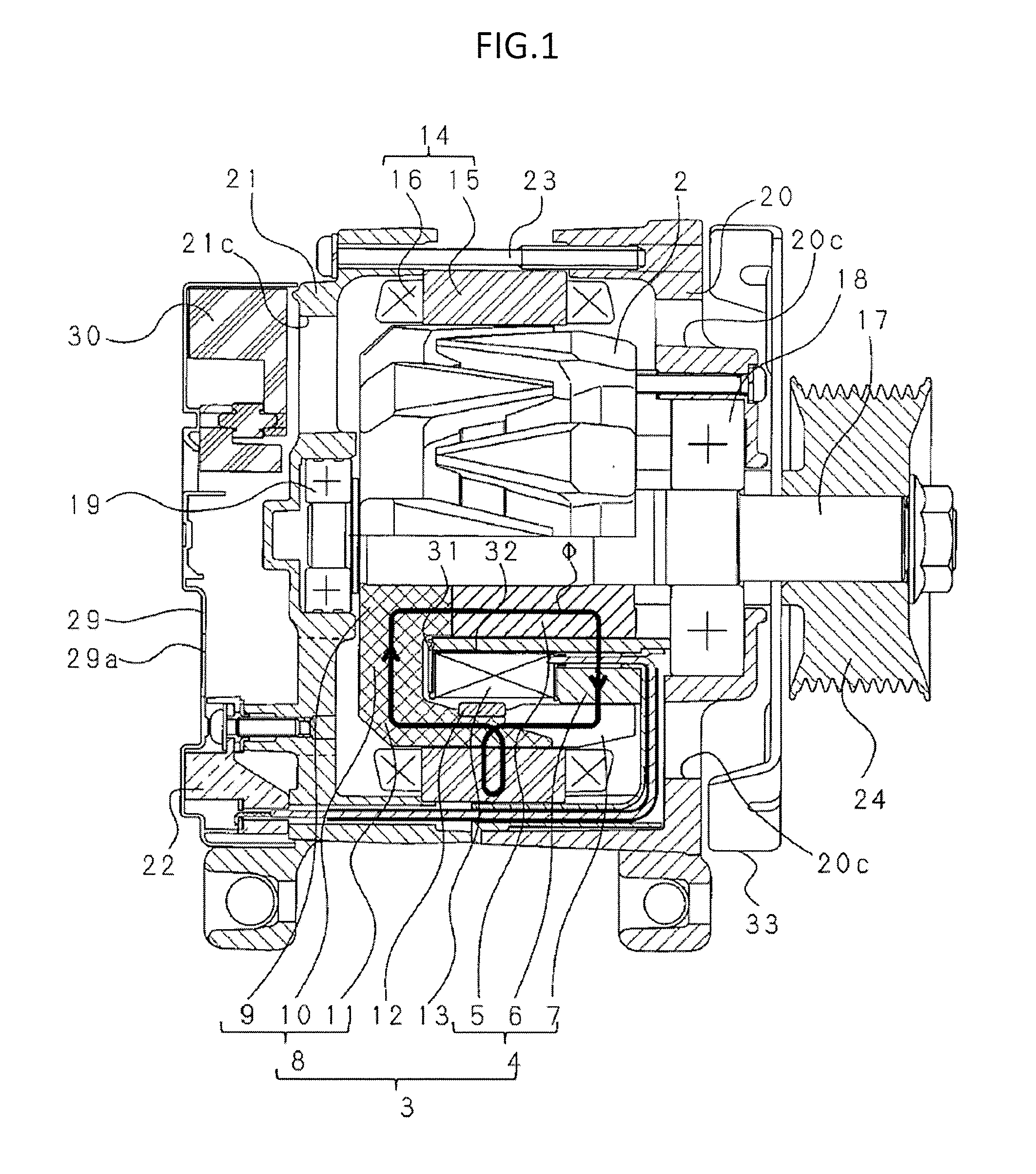
Figure 2 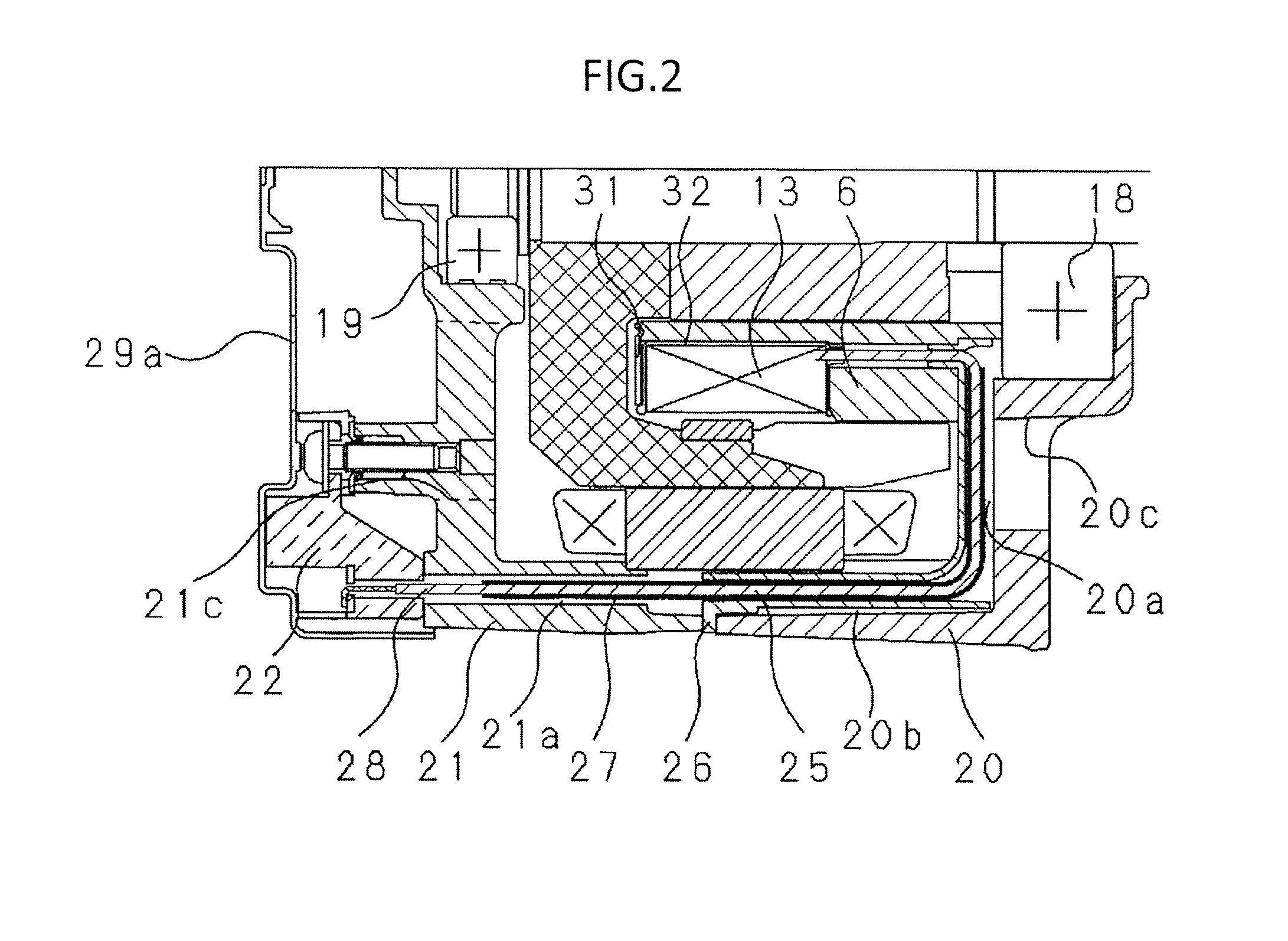
Figure 3
Abstract
Description
BACKGROUND OF THE INVENTION
[0001] 1. Field of the Invention
[0002] The present invention relates to a vehicle brushless AC generator to be mounted on a vehicle, such as an automobile, a bus, and a truck.
[0003] 2. Description of the Related Art
[0004] In a related-art vehicle brushless AC generator, there is known a structure in which a field coil is mounted in a front bracket and a control circuit unit including a voltage regulator and a rectifier is mounted in a rear bracket so that the control circuit unit may be avoided from being thermally affected by a front-side bearing that generates a large amount of heat (see, for example, Japanese Patent Application Laid-open No. Hei 03-195348).
[0005] As another related art, a lead wire as a lead-out portion of the field coil is connected to the voltage regulator from a conductive wire path formed in a stationary yoke section through a first notch groove formed in an outer peripheral-side inner wall surface of a front frame, a through bolt-use no...
Examples
first embodiment
[0021]FIG. 1 is a vertical cross-sectional view illustrating a vehicle brushless AC generator according to a first embodiment of the present invention. FIG. 2 is an enlarged cross-sectional view illustrating a main portion of FIG. 1. FIG. 3 is a front view illustrating a front bracket of FIG. 1. FIG. 4 is a front view illustrating a mold body as a main portion of the vehicle brushless AC generator illustrated in FIG. 1. FIG. 5 is a rear view illustrating the mold body as the main portion of the vehicle brushless AC generator illustrated in FIG. 1. FIG. 6 is a cross-sectional view taken along the line A-A of FIG. 4. FIG. 7 is an enlarged view of the portion Q illustrated in FIG. 6. FIG. 8 is an enlarged view of the portion P illustrated in FIG. 4. FIG. 9 is a cross-sectional view taken along the line B-B of FIG. 5. FIG. 10 is a cross-sectional view taken along the line C-C of FIG. 5.
[0022]Referring to FIGS. 1 to 3, a rotor 2 is provided to a rotary shaft 17, and further, the rotor 2 ...