
Seal device for turbine, turbine, and thin plate for seal device
Patent Information
- Authority / Receiving Office
- US · United States
- Current Assignee / Owner
- Publication Date
- 2018-02-01
Smart Images
Figure 1 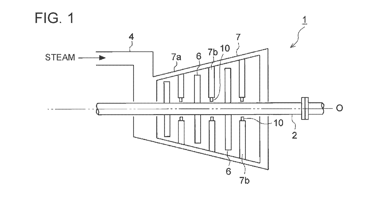
Figure 2 
Figure 3
Abstract
Description
TECHNICAL FIELD
[0001] The present disclosure relates to a seal device for a turbine, a turbine, and a thin plate for a seal device.BACKGROUND ART
[0002] Generally, in a turbine such as a gas turbine and a steam turbine, a seal device for reducing a leakage amount of a fluid that flows from the high-pressure side toward the low-pressure side is disposed between the outer peripheral surface of a rotor and a stator.
[0003] As a type of such seal device, known is a thin-plate seal structure having a plurality of thin plates (leafs) arranged in the circumferential direction of the rotor in a multiple-layered fashion, as disclosed in Patent Documents 1 to 3. The thin plates are normally in contact with the rotor while the turbine is stopped, but the thin-plate tip portions levitate from the rotor peripheral surface while the turbine is in operation, so that the thin plates are mainly in a non-contact state with the rotor. As compared to the labyrinth structure, the thin-plate seal structure is...
Examples
Embodiment Construction
[0051]Embodiments of the present invention will now be described in detail with reference to the accompanying drawings. It is intended, however, that unless particularly specified, dimensions, materials, shapes, relative positions and the like of components described in the embodiments shall be interpreted as illustrative only and not intended to limit the scope of the present invention.
[0052]First, the steam turbine 1 shown in FIG. 1 will be described as an example of a turbine according to the present embodiment. FIG. 1 is a schematic configuration diagram of a steam turbine 1 according to some embodiments.
[0053]As shown in FIG. 1, the steam turbine 1 according to some embodiments is configured to rotary drive the rotor 2 with steam introduced into a casing 7a from a steam inlet 4. In the drawing, the steam discharging mechanism such as an exhaust chamber is not shown.
[0054]Specifically, the steam turbine 1 includes a plurality of rotor blades 6 disposed on the side of the rotor 2...