
Display apparatus
Patent Information
- Authority / Receiving Office
- US · United States
- Current Assignee / Owner
- Publication Date
- 2018-10-04
Smart Images
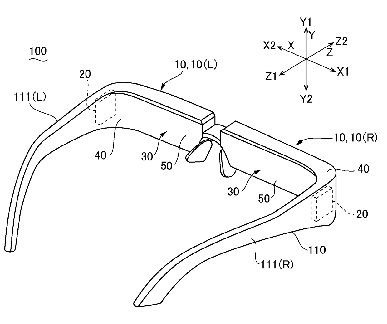
Figure 1 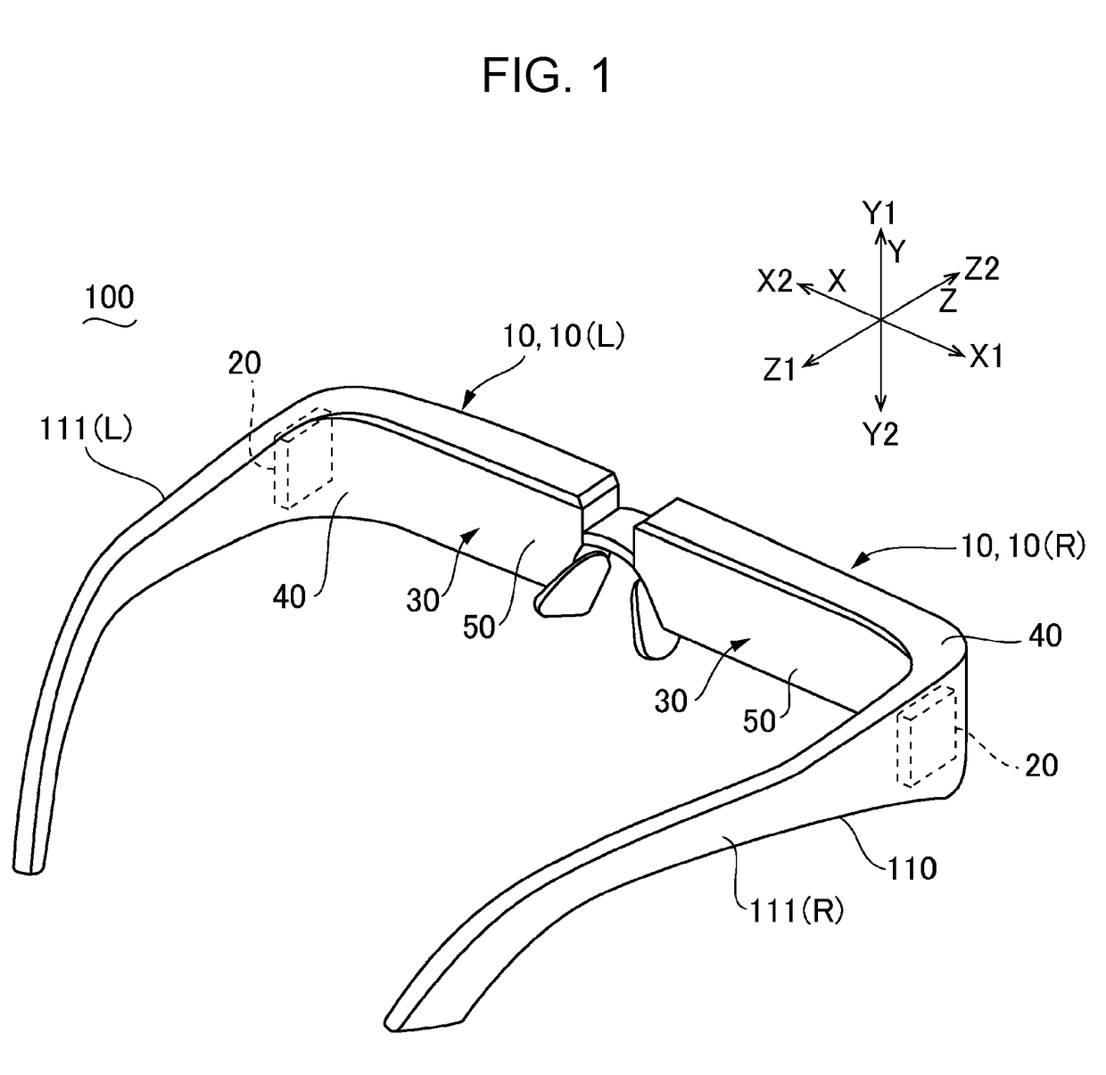
Figure 2 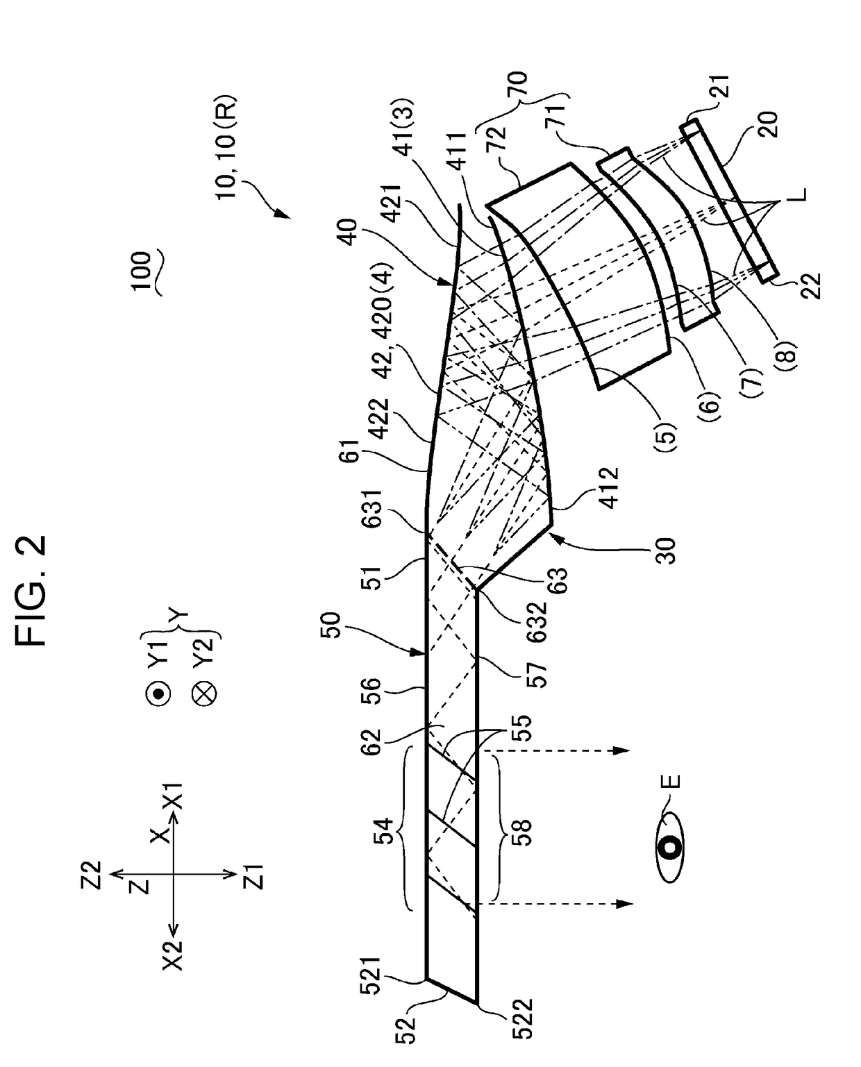
Figure 3
Abstract
Description
BACKGROUND1. Technical Field
[0001] The present disclosure relates to a display apparatus including a light guide system.2. Related Art
[0002] As a display apparatus, a configuration including a light guide system in which a light guide portion extends from a light-incident portion on which image light beams are incident has been proposed, and the image light beams which are incident from the light-incident portion are guided to a light-emitting portion via the light guide portion (refer to JP-A-2017-3845). Since a light-incident curved surface and a light-reflective curved surface are formed on the light-incident portion, the image light beams are incident from the light-incident curved surface, are reflected between the light-reflective curved surface and the light-incident curved surface, and then are guided to the light guide portion. On the other hand, a light guide system including a light guide portion in which a plurality of partial reflection layers are disposed parallel to eac...
Examples
first embodiment
Overall Configuration
[0025]FIG. 1 is an explanatory view schematically illustrating an example of an appearance of a display apparatus 100 according to a first embodiment. The display apparatus 100 illustrated in FIG. 1 is configured with a see-through type eye glass display or the like, and includes a frame 110 provided with temples 111(R) and 111(L) on left and right sides thereof. In the display apparatus 100, a display unit 10 to be described is supported by the frame 110, and an image emitted from the display unit 10 is recognized by a user, as a virtual image. In the present embodiment, the display apparatus 100 includes a right-eye display unit 10(R) and a left-eye display unit 10(L) as the display unit 10. The right-eye display unit 10(R) and the left-eye display unit 10(L) have the same configuration, and are disposed symmetrically in a right-left direction. Thus, in the following description, the right-eye display unit 10(R) will be mainly described, and a description of t...
second embodiment
[0057]FIG. 7 is a plan diagram of the optical system of the display apparatus 100 according to a second embodiment. Since the basic configuration of the present embodiment and each embodiment to be described is the same as that of the first embodiment, the same reference numerals are given to the common portions, and a description thereof will be omitted.
[0058]As illustrated in FIG. 7, even in the present embodiment, similar to the first embodiment, the light-incident portion 40 is formed of the first transparent member 61, the portion 54 of the light guide portion 50 at which at least the plurality of partial reflection layers 55 are formed is formed of the second transparent member 62 which is surface-bonded to the first transparent member 61 via the bonding surface 63 (first bonding surface) in the first direction X. In the present embodiment, the bonding surface 63 is disposed at a portion between the plurality of partial reflection layers 55 and one end 51 in the light guide po...
third embodiment
[0059]FIG. 8 is a plan diagram of the optical system of the display apparatus 100 according to a third embodiment. As illustrated in FIG. 8, even in the present embodiment, similar to the first embodiment, the light-incident portion 40 is formed of the first transparent member 61, the portion 54 of the light guide portion 50 at which at least the plurality of partial reflection layers 55 are formed is formed of the second transparent member 62 which is surface-bonded to the first transparent member 61 via the bonding surface 63 (first bonding surface) in the first direction X. In the present embodiment, the bonding surface 63 is positioned at a position overlapping with the partial reflection layer 55 positioned closest to the one end 51 side among the plurality of partial reflection layers 55. Therefore, similar to the first embodiment, the bonding surface 63 is inclined in the same direction as that of the partial reflection layer 55. Other configurations are the same as in the fi...