
Vehicle Wheel Axle Assembly
a technology for axles and vehicles, applied in the direction of axle suspensions, release mechanisms, hubs, etc., can solve the problems of inability to retain the control shaft, inability to service and clean the control shaft, and inability to maintain the control shaft, so as to minimize the frustration, complexity, skill requirements, and eliminate the trial and error
Patent Information
- Authority / Receiving Office
- US · United States
- Patent Type
- Applications(United States)
- Current Assignee / Owner
- Publication Date
- 2020-01-16
Smart Images
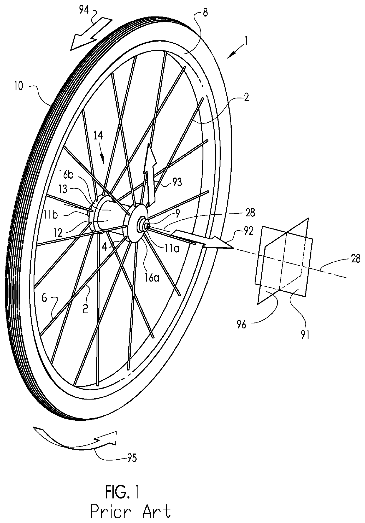
Figure 1 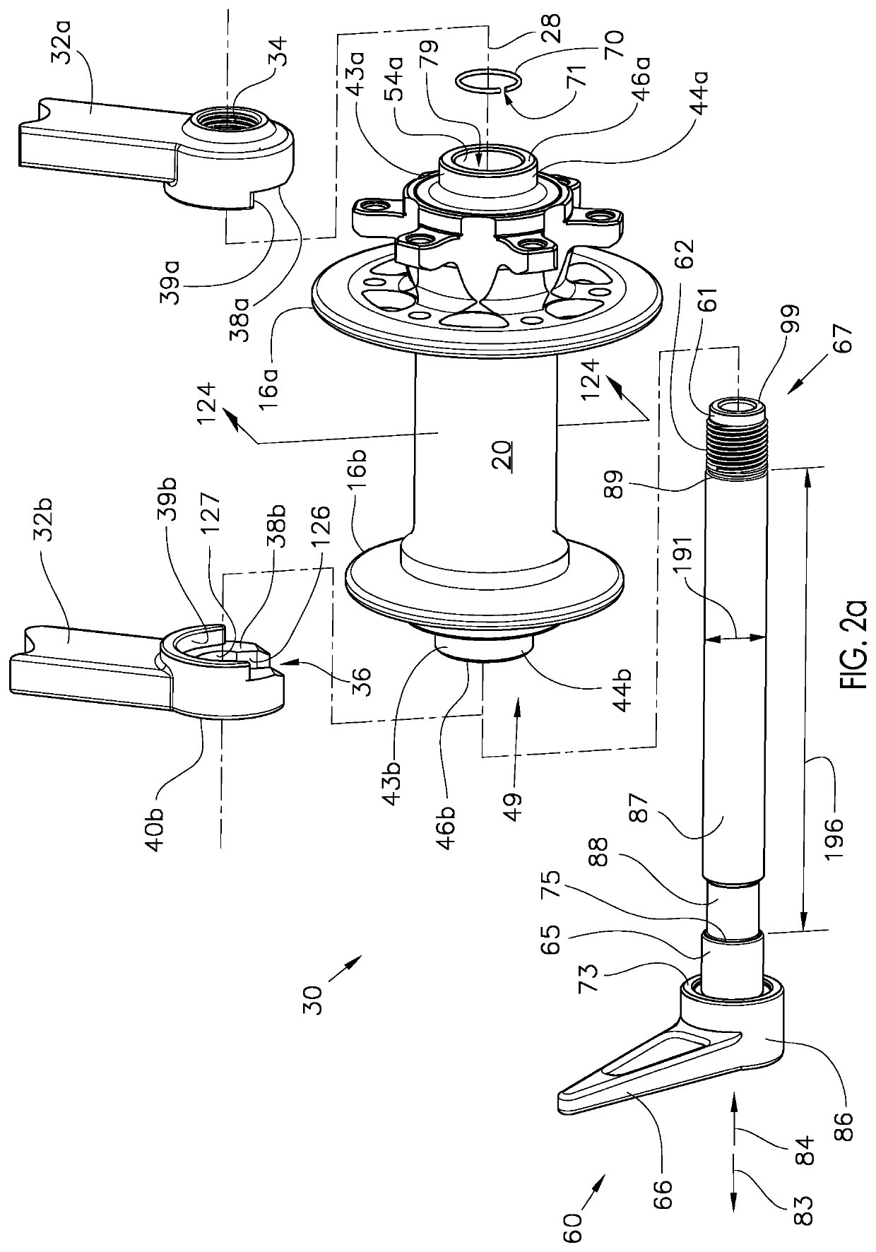
Figure 2 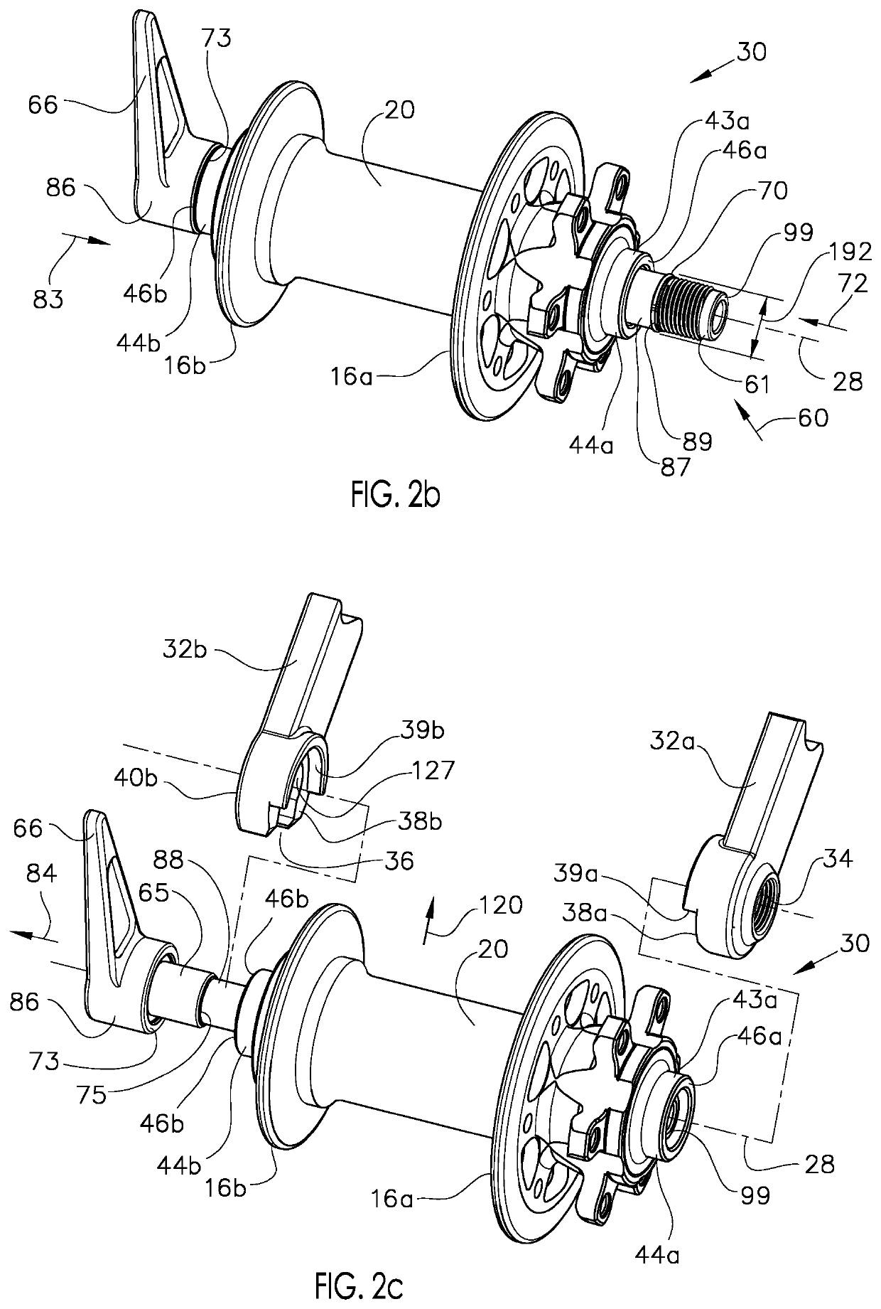
Figure 3
Abstract
Description
CROSS-REFERENCE TO RELATED APPLICATION
[0001] This application claims priority of U.S. Provisional Patent Application 62 / 700,925, filed Jul. 20, 2018.
[0002] This application is also a Continuation-In-Part of U.S. patent application Ser. No. 16 / 377,167 filed Apr. 6, 2019, which is currently pending.
[0003] U.S. patent application Ser. No. 16 / 377,167 claims priority of U.S. Provisional Patent Application 62 / 653,575, filed Apr. 6, 2018, which has expired.
[0004] U.S. patent application Ser. No. 16 / 377,167 is a Continuation-In-Part of U.S. patent application Ser. No. 15 / 681,410, filed Aug. 20, 2017, which is currently pending.
[0005] U.S. patent application Ser. No. 15 / 681,410 claims priority of U.S. Provisional Patent Application 62 / 381,155, filed Aug. 30, 2016 and entitled “VEHICLE WHEEL AXLE ASSEMBLY”, which has expired.
[0006] U.S. patent application Ser. No. 15 / 681,410 is also a Continuation-In-Part of U.S. patent application Ser. No. 14 / 974,228, filed Dec. 18, 2015, which is abandoned.
[0007] ...
Examples
Embodiment Construction
[0055]FIG. 1 describes the basic configuration of an exemplary prior art vehicle wheel, in particular, a bicycle wheel 1, as well as a description of the direction conventions used throughout this disclosure. The hub assembly 14 includes a rotatable hub shell 12 and a stationary axle 9, with bearings (not shown) to facilitate rotation of the hub shell 12 about the axial axis 28. The hub shell 12 includes a hub body 13 with at least two axially spaced hub flanges 16a and 16b, each of which include a means for connecting with the spokes (not shown). The axle 9 includes end faces 11a and 11b to interface with the dropouts (not shown). The axial axis 28 is the axial centerline of rotation of the bicycle wheel 1. The hub flanges 16a and 16b may be contiguous with the hub shell 12 or may be separately formed and assembled to the hub body 13 portion of the hub shell 12. The spokes 2 are affixed to the hub flanges 16a or 16b at their first end 4 and extend to attach the rim 8 at their secon...