
Vehicle drive device
a technology of drive device and drive rail, which is applied in the direction of engine-driven generator propulsion, charging station, transportation and packaging, etc., can solve the problems of power not being obtained for driving rail vehicles, internal combustion engine stall condition, etc., and achieve the effect of suppressing internal combustion engine overload and improving output responsiveness
Patent Information
- Authority / Receiving Office
- US · United States
- Patent Type
- Applications(United States)
- Current Assignee / Owner
- Publication Date
- 2020-11-19
Smart Images
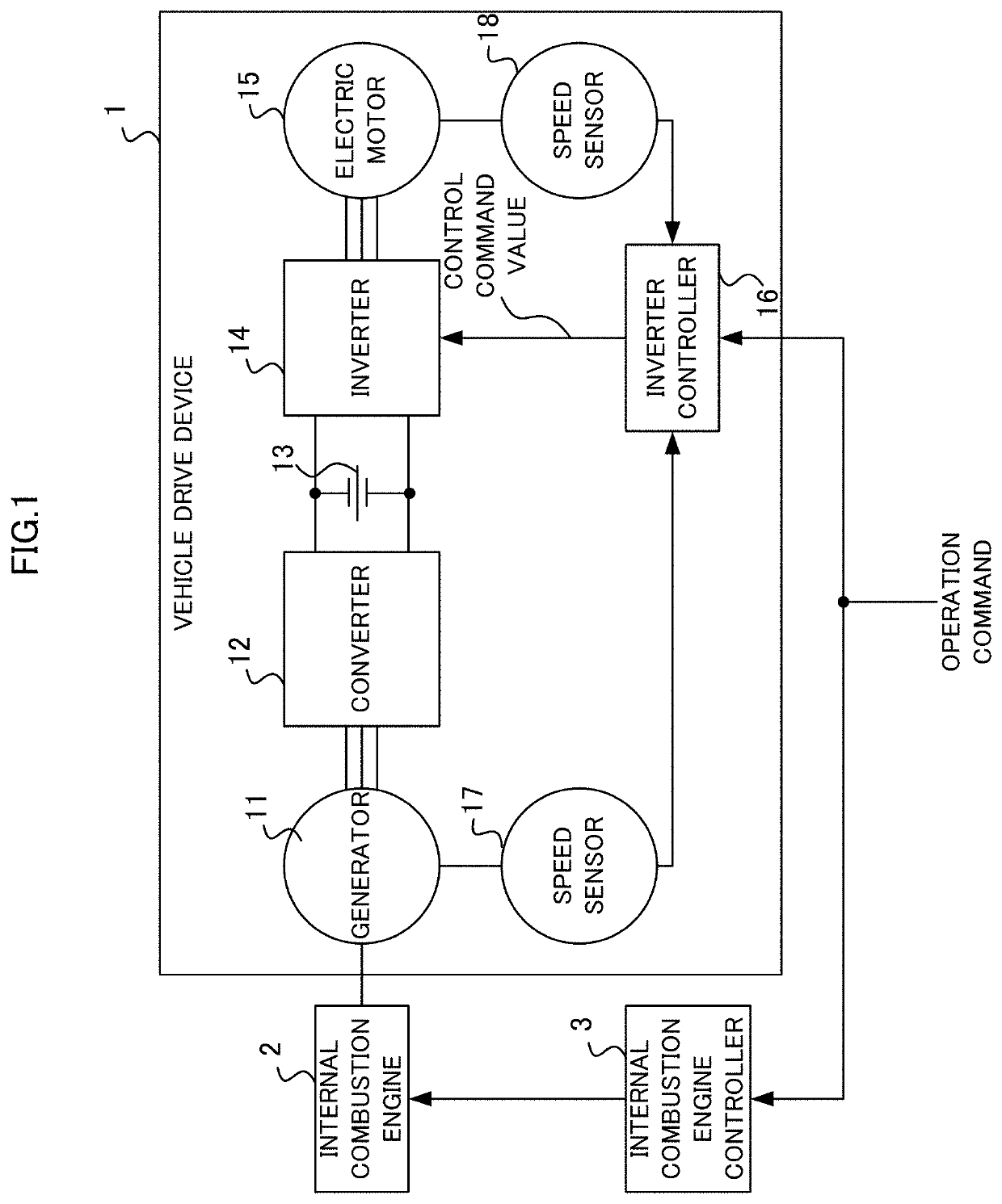
Figure 1 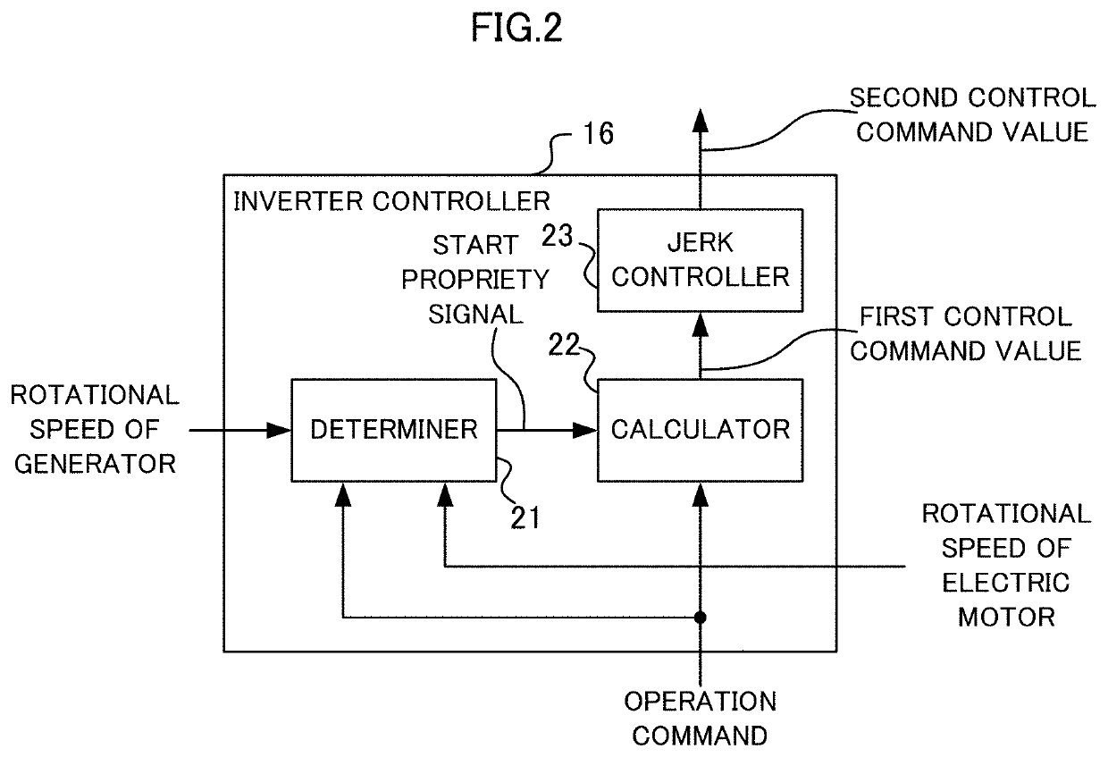
Figure 2 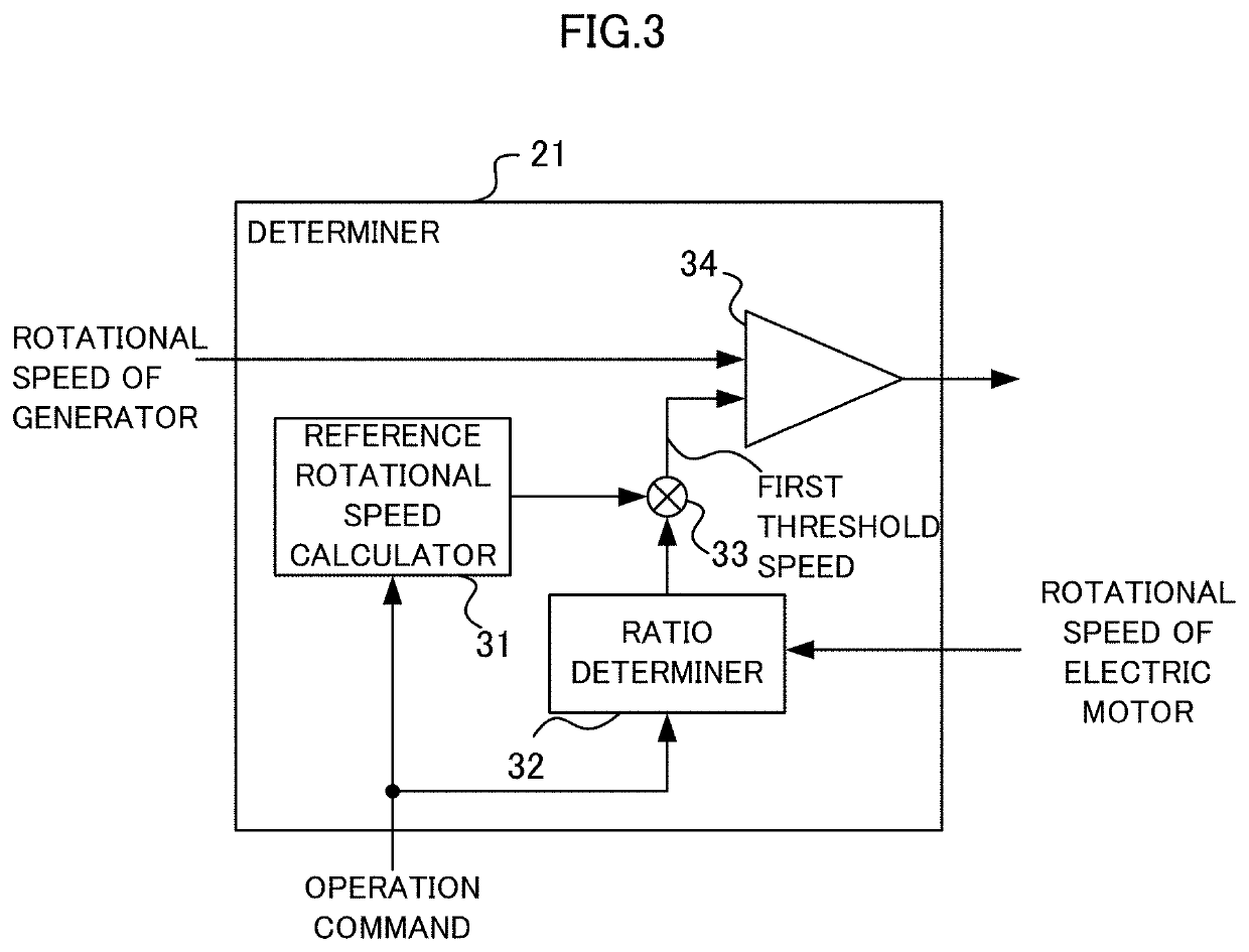
Figure 3
Abstract
Description
TECHNICAL FIELD
[0001] The present disclosure relates to a vehicle drive device.BACKGROUND ART
[0002] Some rail vehicles run using an internal combustion engine as a power source. An output of the internal combustion engine is controlled in accordance with a notch command input from a master controller provided in a cab. Examples of vehicle drive devices that drive the rail vehicles include a vehicle drive device that uses a generator and an electric motor. The vehicle drive devices each include the generator that is driven by an internal combustion engine to output alternating-current (AC) power, a converter that converts the AC power output by the generator into direct-current (DC) power, and an inverter that converts the DC power into AC power to supply the AC power to the electric motor. The vehicle drive device further includes a control device that controls the output of the inverter in order to obtain an output of the electric motor in accordance with the notch command. As descri...
Examples
embodiment 1
[0025]A vehicle drive device 1 according to Embodiment 1 of the present disclosure, which is illustrated in FIG. 1, drives a rail vehicle using an internal combustion engine 2 as a power source. The internal combustion engine 2 as the power source is controlled by an internal combustion engine controller 3. An operation command is input to the internal combustion engine controller 3. The internal combustion engine controller 3 acquires the operation command from a master controller provided in a non-illustrated cab. The internal combustion engine controller 3 controls the internal combustion engine 2 by (i) calculating an internal combustion engine notch command for the internal combustion engine 2 in accordance with the operation command and (ii) outputting the internal combustion engine notch command to the internal combustion engine 2. The internal combustion engine notch command is a command indicating a rotational speed of the internal combustion engine 2. The internal combusti...
embodiment 2
[0048]In Embodiment 1, in order that the value R indicating the responsiveness of the electric motor 15 has a negative correlation with the rotational speed of the electric motor 15 at the time when the operation command changes, the first threshold speed ωth is changed using the ratio α having a positive correlation with the rotational speed of the electric motor 15 at the time when the operation command changes. A method for making the value R have the above-described negative correlation is freely selected. For example, the second control command value may be changed based on the rate of change β that changes in accordance with the rotational speed of the electric motor 15. Embodiment 2 in which both the ratio α and the rate of change β are changed is described below.
[0049]The configuration of the vehicle drive device 1 according to Embodiment 2 of the present disclosure is similar to that of the vehicle drive device 1 according to Embodiment 1. As illustrated in FIG. 7, the inve...
embodiment 3
[0055]In Embodiments 1 and 2, in order that the value R indicating the responsiveness of the electric motor 15 has a negative correlation with the rotational speed of the electric motor 15 at the time when the operating command changes, the first threshold speed ωth1 is changed using the ratio α having a positive correlation with the rotational speed of the electric motor 15 at the time when the operation command changes. The method for making the value R have the above-described negative correlation is freely selected. For example, the ratio α may be taken to be a fixed value, and the second control command value may be changed based on the rate of change β that changes in accordance with the rotational speed of the electric motor 15. Embodiment 3 in which the ratio α is a fixed value and the rate of change β is changed in accordance with the rotational speed of the electric motor 15 is described below.
[0056]The configuration of a vehicle drive device 1 according to Embodiment 3 of...