
Continuously variable transmission, endless flexible belt for torque transmission and adjustable pulley
Patent Information
- Authority / Receiving Office
- US · United States
- Current Assignee / Owner
- Publication Date
- 2005-08-09
- Estimated Expiration
- Not applicable · inactive patent
Smart Images
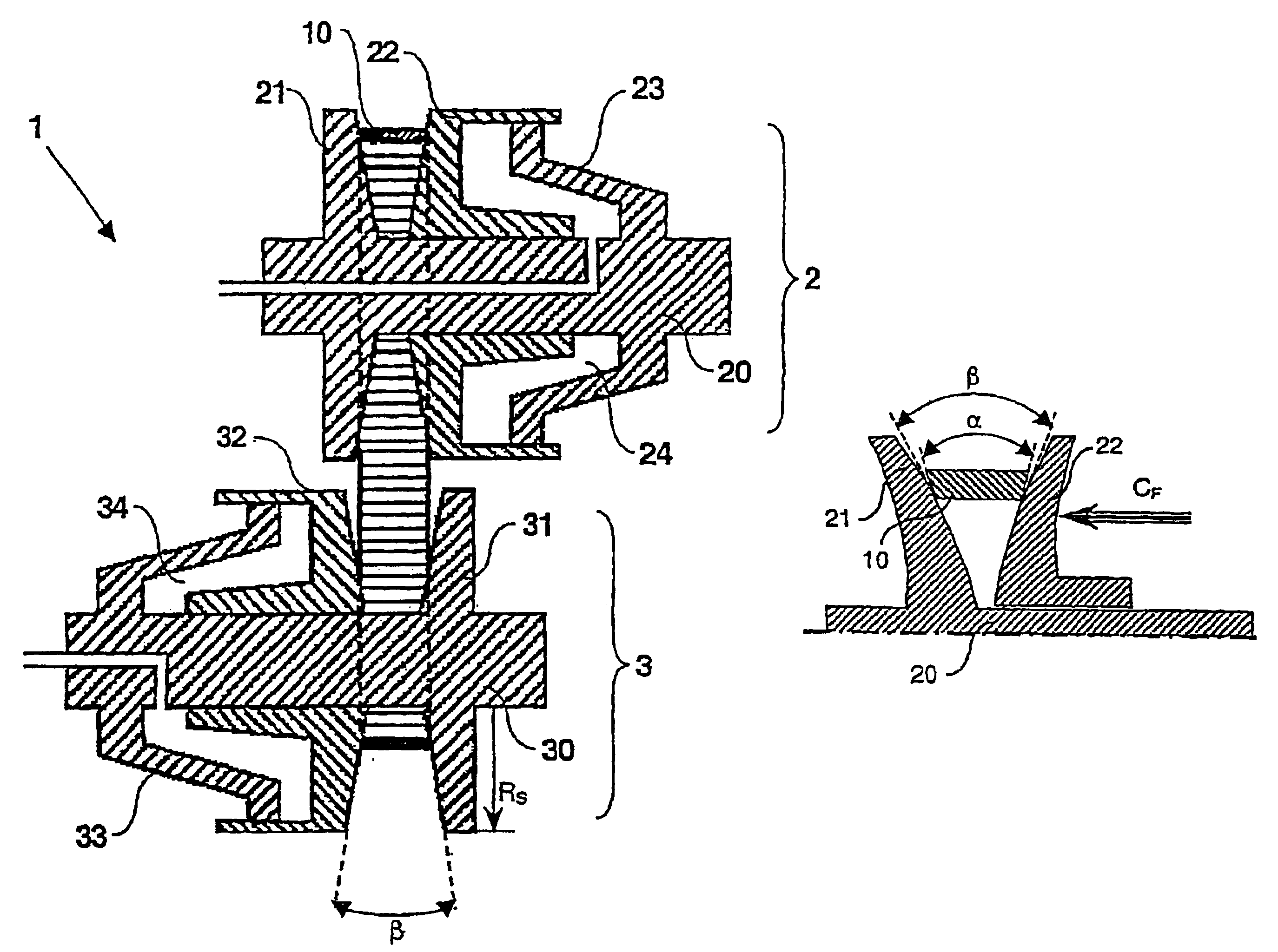
Figure 1 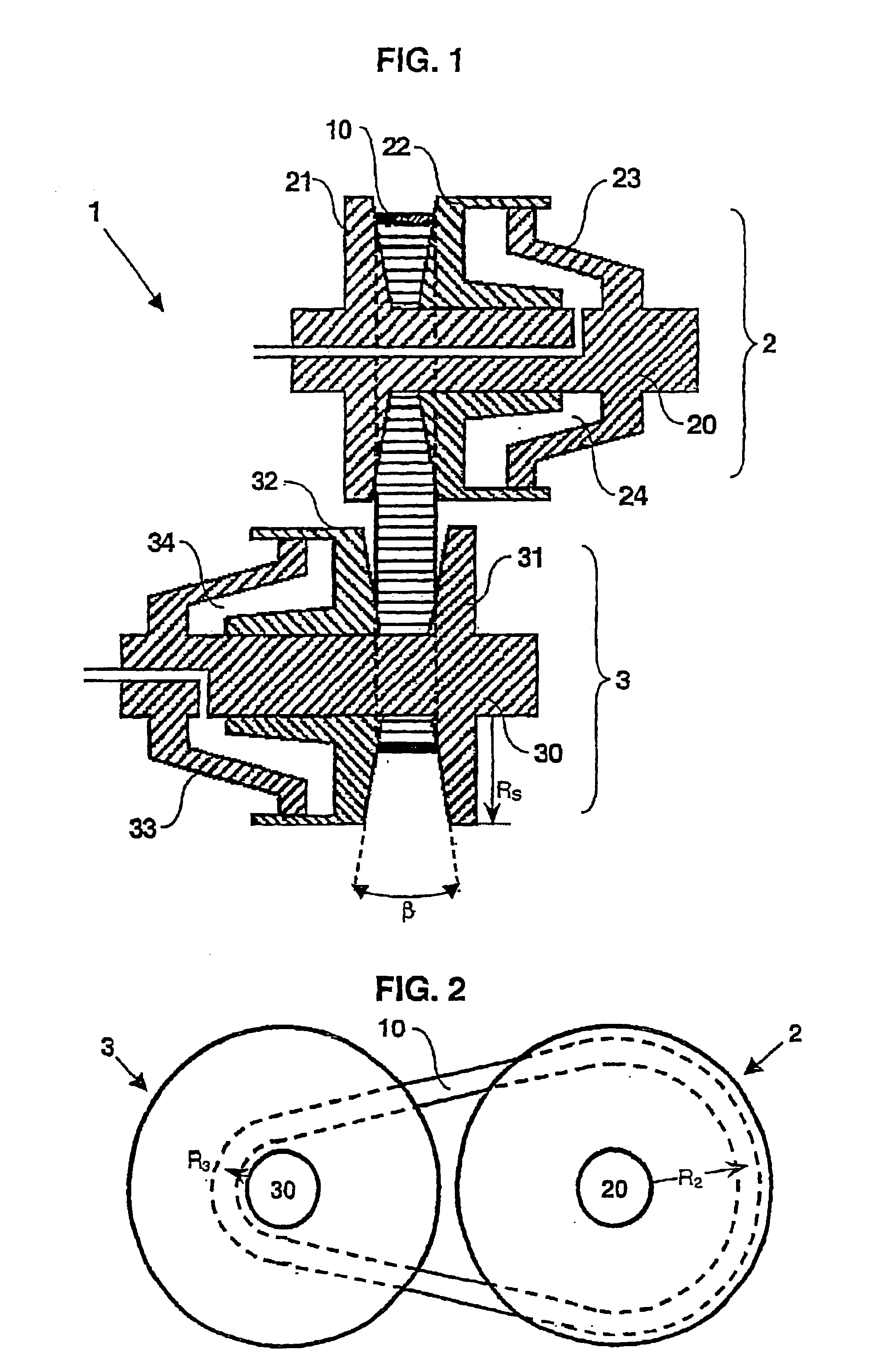
Figure 2 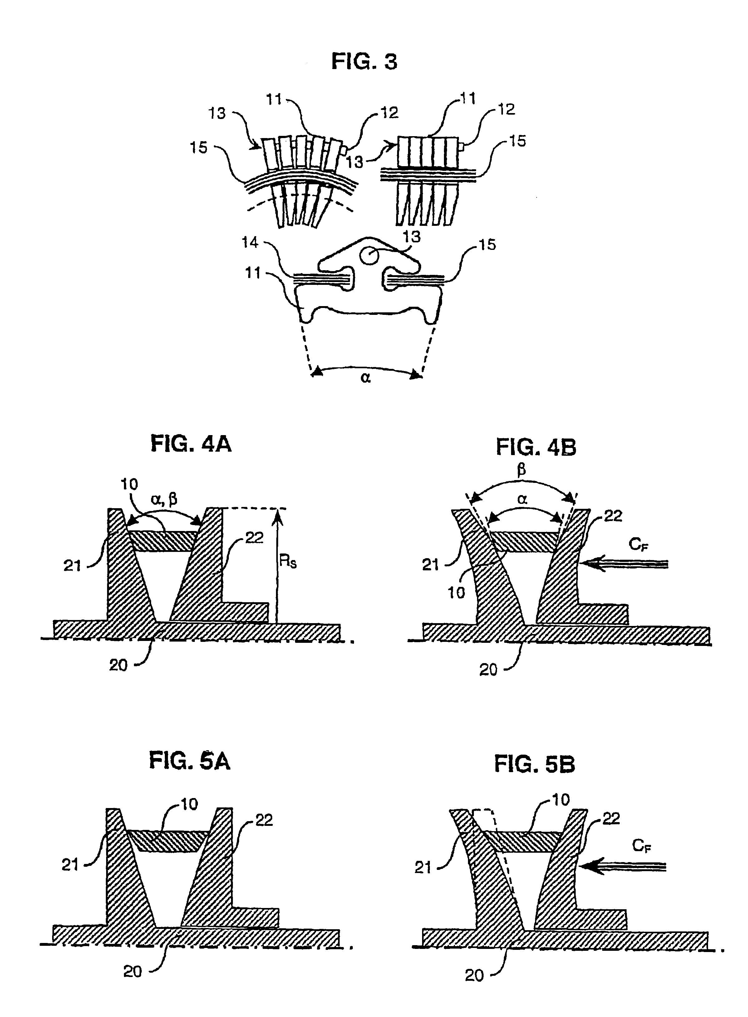
Figure 3
Abstract
Description
CROSS REFERENCE TO RELATED APPLICATIONS
[0001] This patent results from a national stage of PCT / EP01 / 05921 filed May 23, 2001 and claims priority to European Application No. 00 / 201849.7 filed May 26, 2000.BRIEF DESCRIPTION OF THE INVENTION
[0002] The present invention relates to a belt-type continuously variable transmission, alternatively denoted as a CVT, provided with an adjustable pulley and an endless flexible belt. The invention further relates to an endless flexible belt for torque transmission, such as a push-type drive belt, and to an adjustable pulley.DESCRIPTION OF THE RELATED ART
[0003] The CVT of the present type is generally known, for example from EP-A-0.950.837, and comprises a first adjustable pulley, a second adjustable pulley and an endless flexible belt, such as a push-type drive belt known from EP-A-0.962.679, a chain and the like, for transmitting torque between the pulleys at a variable transmission ratio. In the known CVT, with the application of a clamping force, ...
Examples
Embodiment Construction
[0028]In FIG. 1 a CVT 1 according to the known art is shown. The CVT 1 comprises an input pulley 2 and an output pulley 3, each pulley 2; 3 comprising a set of two frusto-conical sheaves 21, 22; 31, 32 provided on an input pulley shaft 20 and on an output pulley shaft 30 respectively, and a flexible belt 10. The sheaves have a radial dimension RS. The sheaves 21, 22; 31, 32 of a pulley 2; 3 may be urged towards each other under the influence of a hydraulic pressure exerted in a piston / cylinder assembly 23, 24; 33, 34 associated with the respective pulley 2; 3. As a result thereof, a clamping force CF is effected between the flexible belt 10 and the pulley sheaves 21, 22; 31, 32, of each of the pulleys, so that torque may be transmitted between said pulley 2; 3 by the belt 10 through friction.
[0029]Each sheave 21, 22, 31, 32 has a sheave face, whereby the sheave faces of a pulley 2; 3 are mutually oriented at a pulley angle β, as indicated in FIG. 1, such that they define an essentia...