
Method and circuit for regulating power in a high intensity discharge lamp
a high intensity discharge and lamp technology, applied in the field of circuits for powering discharge lamps, can solve the problems of increased size and higher cost, and achieve the effect of avoiding the associated energy loss, size, weight and cost, and reliability regulating lamp power
Patent Information
- Authority / Receiving Office
- US · United States
- Patent Type
- Patents(United States)
- Current Assignee / Owner
- Publication Date
- 2007-03-06
- Estimated Expiration
- Not applicable · inactive patent
Smart Images
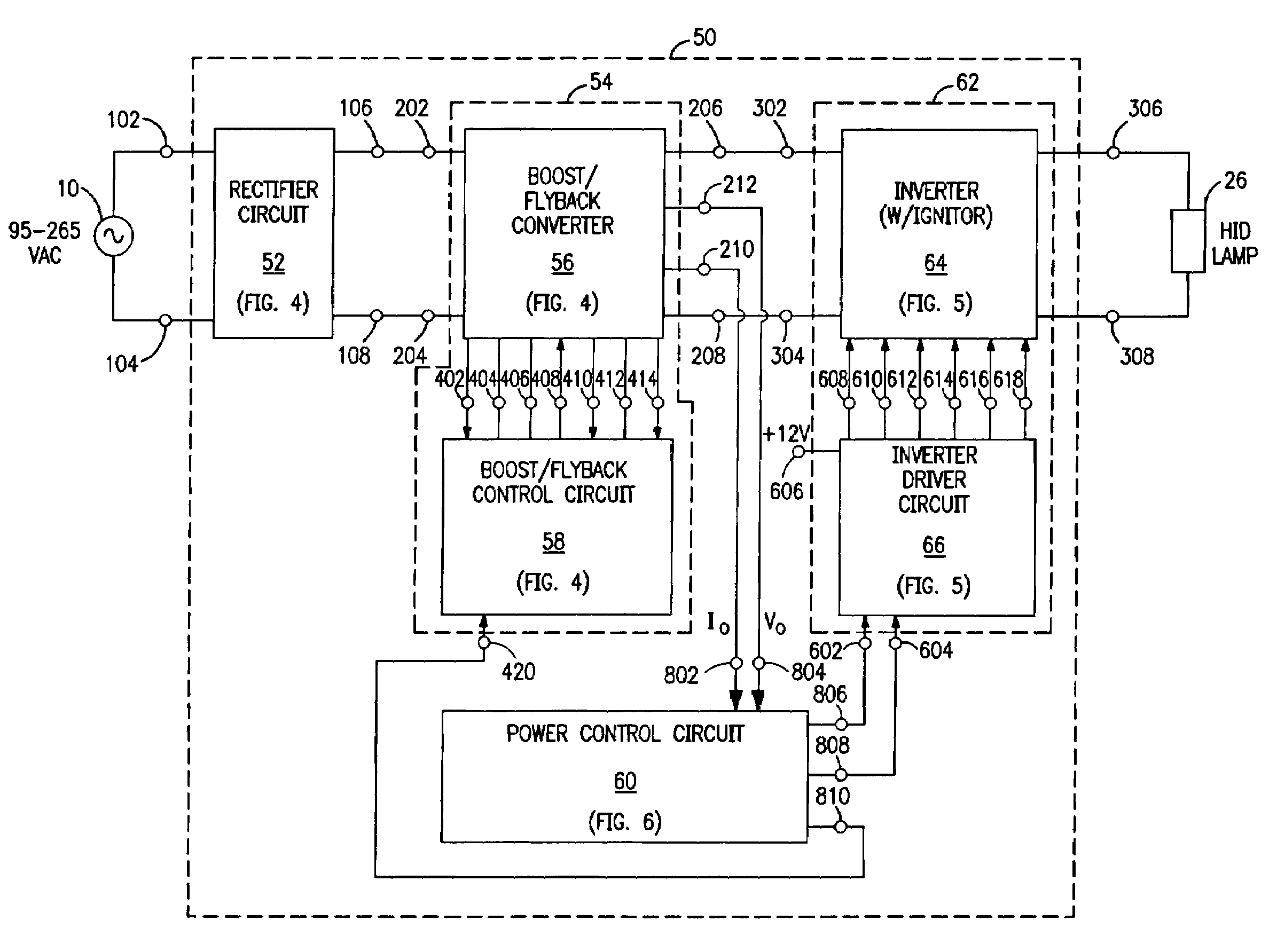
Figure 1 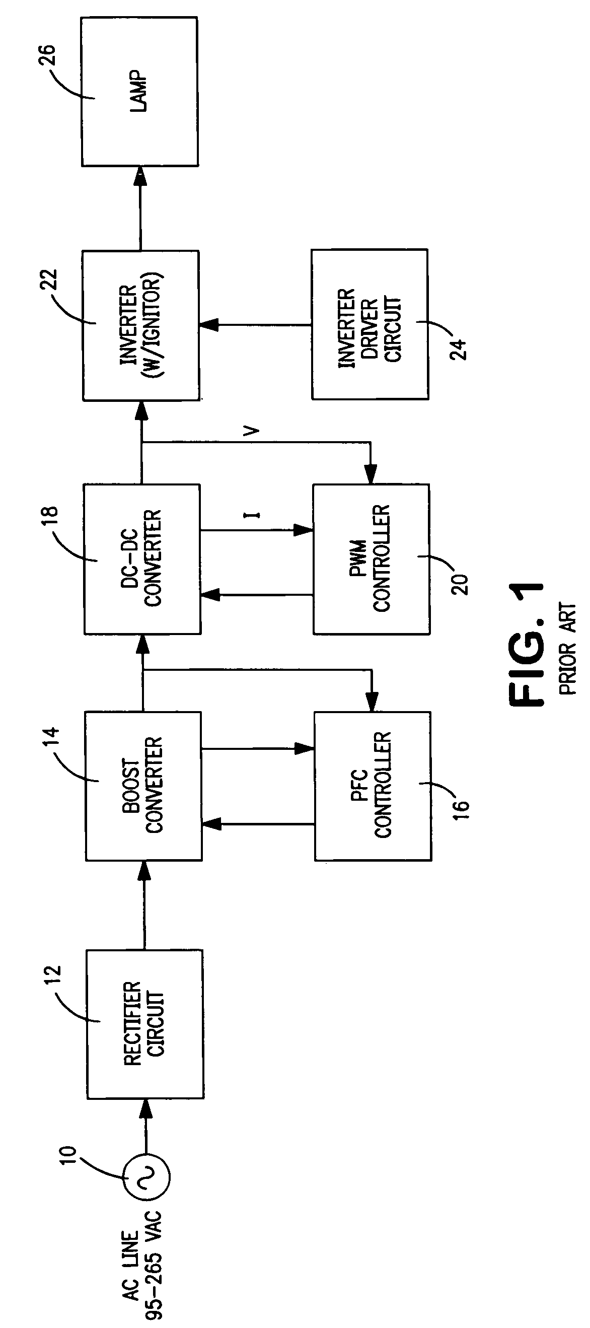
Figure 2 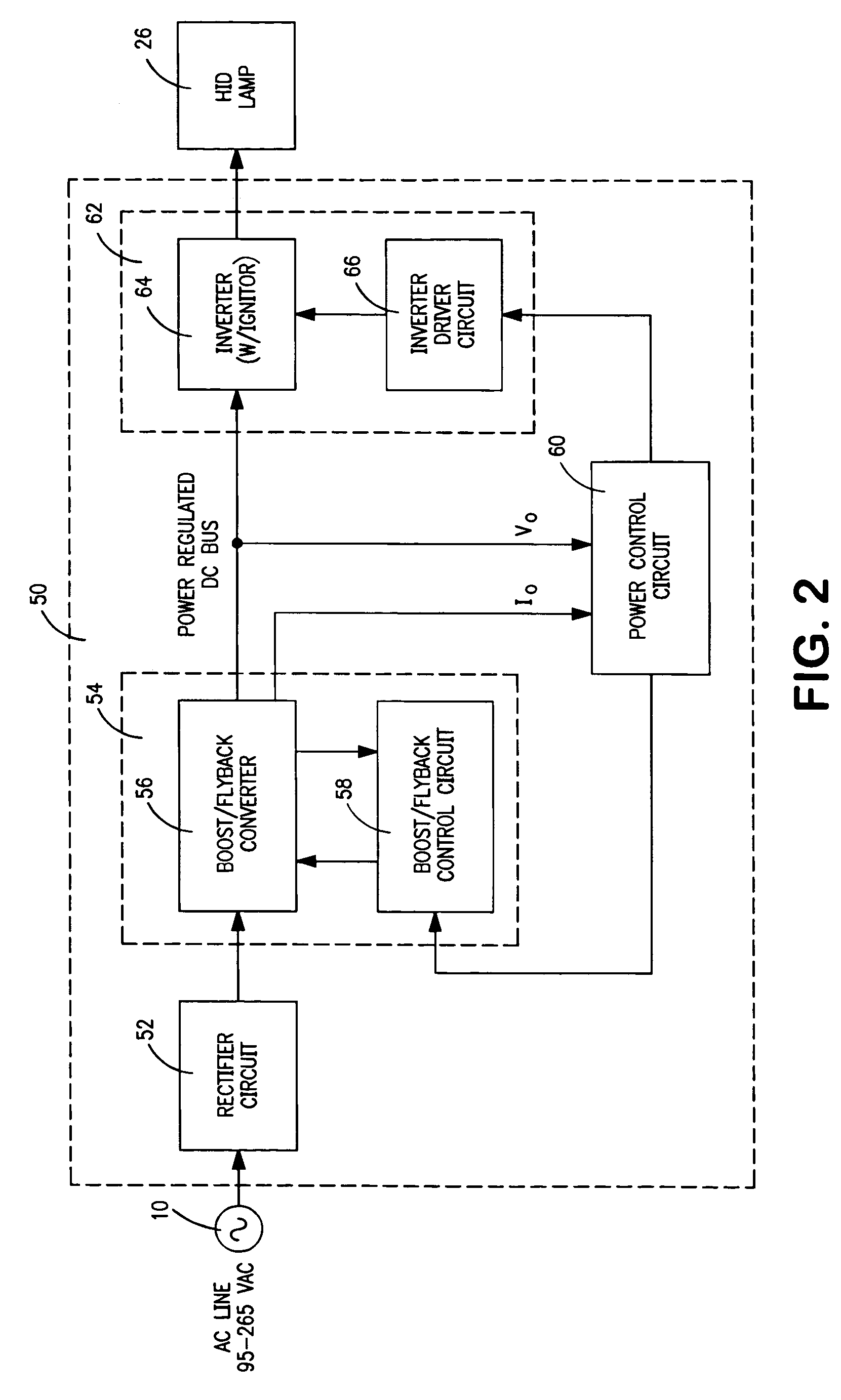
Figure 3
Abstract
Description
FIELD OF THE INVENTION
[0001] The present invention generally relates to circuits for powering discharge lamps, and more particularly to a circuit and method for regulating power in a high intensity discharge lamp.BACKGROUND OF THE INVENTION
[0002] In starting a high intensity discharge (HID) lamp, the lamp experiences three phases. These phases include breakdown, glow discharge, and thermionic arc. Breakdown requires a high voltage to be applied between the electrodes of the lamp. Following breakdown, the voltage must be high enough to sustain a glow discharge and heat the electrode to thermionic emission. Once thermionic emission commences, current must be maintained in the run-up phase until the electrodes reach a steady-state temperature. After achieving the arc state, the lamp can be operated with a lower level of current in the steady state operating mode.
[0003] For ignition of the lamp, the lamp must be provided with a high voltage for a specified duration in the pre-breakdown per...
Examples
Embodiment Construction
[0023]The various embodiments of the present invention relate to an electronic ballast and method of controlling power to a high intensity discharge lamp by providing power factor correction, power regulation and AC-DC conversion in a single power processing stage. An electronic ballast is employed to power an HID lamp from a universal input AC line voltage. Average lamp power is regulated by a micro-controller driving a Transition Mode (TM) or critical conductance mode power factor controller. The ballast preferably includes an active power factor corrector circuit configured as combination boost and flyback converter. The output current and voltage of the combined boost and flyback converter are varied to regulate the lamp power. Either the DC output bus power can be regulated, or with the addition of a current and voltage transformer, the inverter AC output power can be regulated. Because the average is taken of a digital PWM output voltage based on a table lookup and is used to ...