
Device for connecting component parts, comprising a blind rivet fastener
Patent Information
- Authority / Receiving Office
- US · United States
- Current Assignee / Owner
- Publication Date
- 2007-06-05
Smart Images
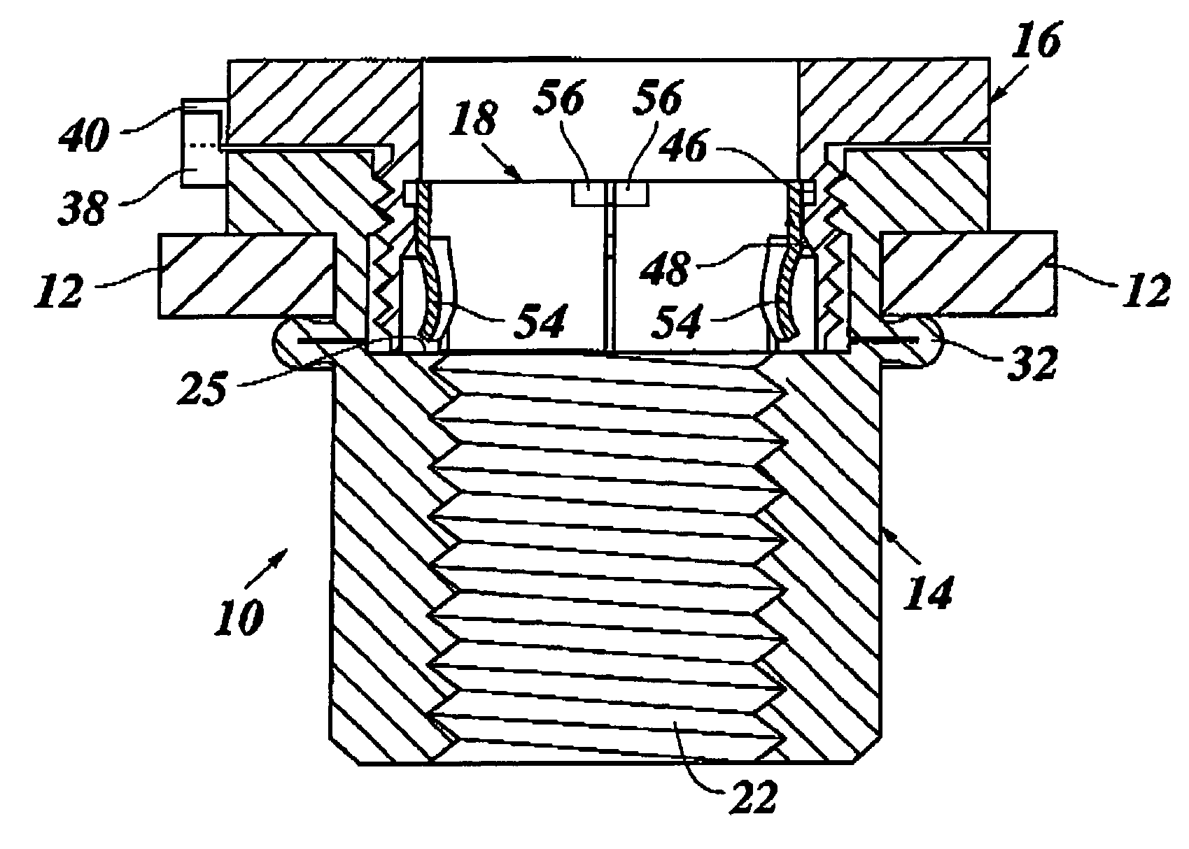
Figure 1 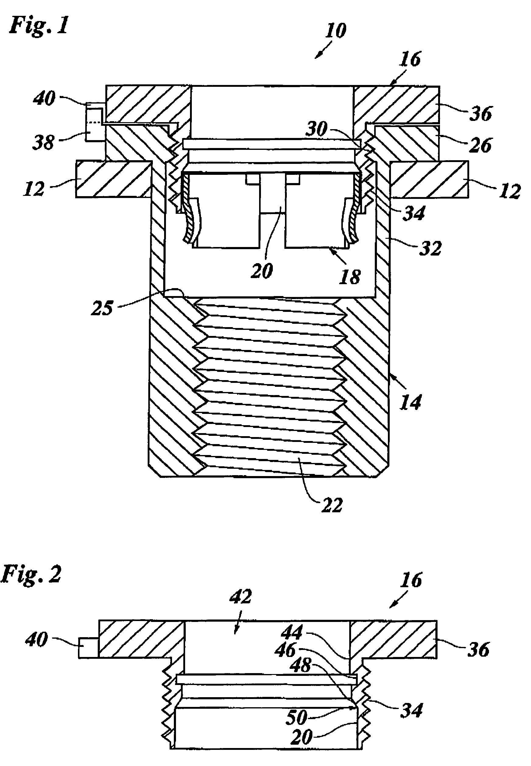
Figure 2 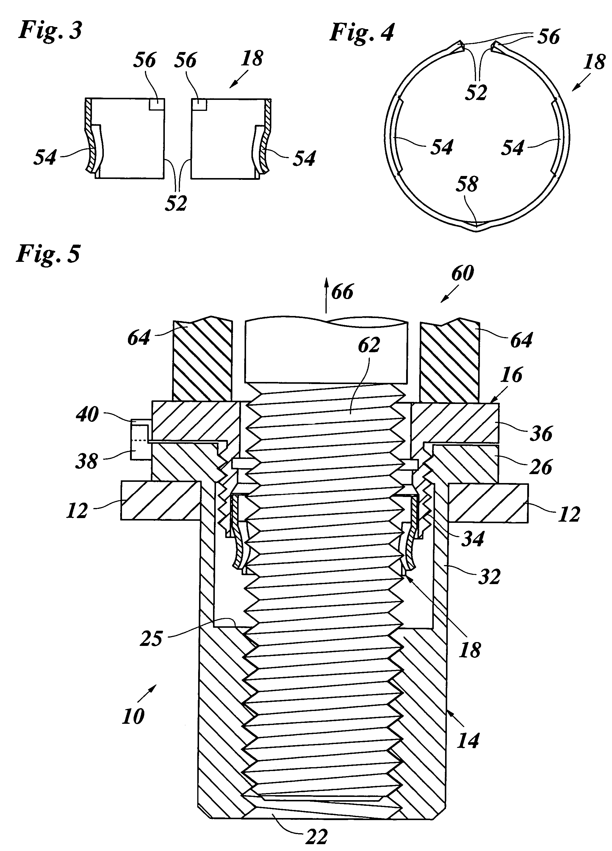
Figure 3
Abstract
Description
BACKGROUND OF THE INVENTION
[0001] The invention relates to a device for connecting component parts, comprising: a blind rivet nut adapted to be anchored in one of the components parts by means of a riveter having a threaded stud; a spacer held in threaded engagement with said blind rivet nut, said spacer being brought into a support position at the other-of said component parts by being screwed out of said blind rivet nut; a connecting screw adapted to be screwed into said blind rivet nut, and a torque-transmitting intermediate member that is accommodated in a receptacle of said spacer and transmits a torque onto the spacer when the connecting screw is screwed-in.
[0002] Devices of this type are known, which serve for connecting two component parts with a certain spacing relative to one another by means of a connecting screw, without the component parts being drawn together when the connecting screw is tightened. Conventionally, for establishing the connection, the blind rivet nut is a...
Examples
Embodiment Construction
[0032]FIG. 1 shows a connecting device 10 in a supply condition, inserted in a first component part 12. The connecting device 10 is formed by a blind rivet nut 14 held at the component part 12, a spacer 16 screwed into the blind rivet nut 14, and an intermediate member in the form of an elastic ring 18 that has been inserted in a receptacle 20 on the bottom side of the spacer 16.
[0033]The blind rivet nut 14 has in its lower part a right-handed thread 22 for a connecting screw 24 (FIG. 8) the thread being surrounded at its top end by an annular support surface 25 for the elastic ring 18. At the top end, the blind rivet nut 14 engages an outer surface of the component part 12 with a flange 26. A left-handed thread 30 is formed in the top part of the blind rivet nut 14. Below the left-handed thread 30 and the flange 26, a thinner wall 32 forms a deformation portion the function of which will be explained below in conjunction with FIG. 6.
[0034]The spacer 16, which has been shown more cl...