
Gangable cable support with improved stiffness
a cable support and stiffness technology, applied in the field of cable supports, can solve the problems of not providing a balanced support and evenly distributed weight, affecting the service life of the cable, so as to improve the stiffness of the support and improve the withstanding of bending moments
Patent Information
- Authority / Receiving Office
- US · United States
- Current Assignee / Owner
- Publication Date
- 2008-08-05
Smart Images
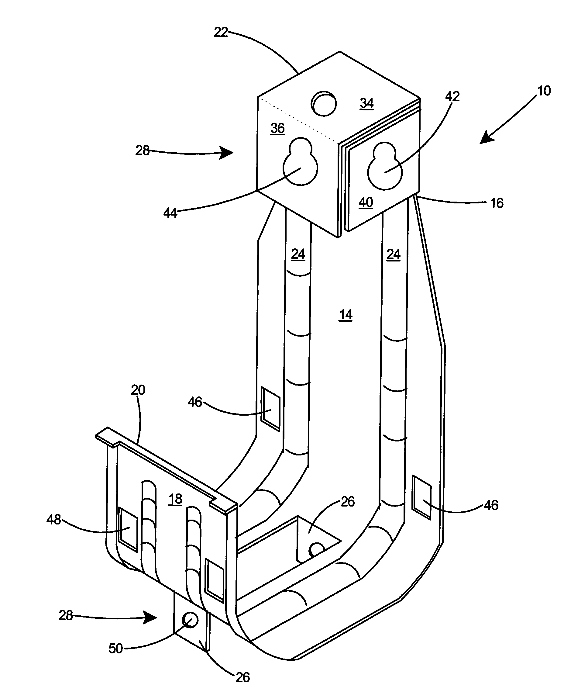
Figure 1 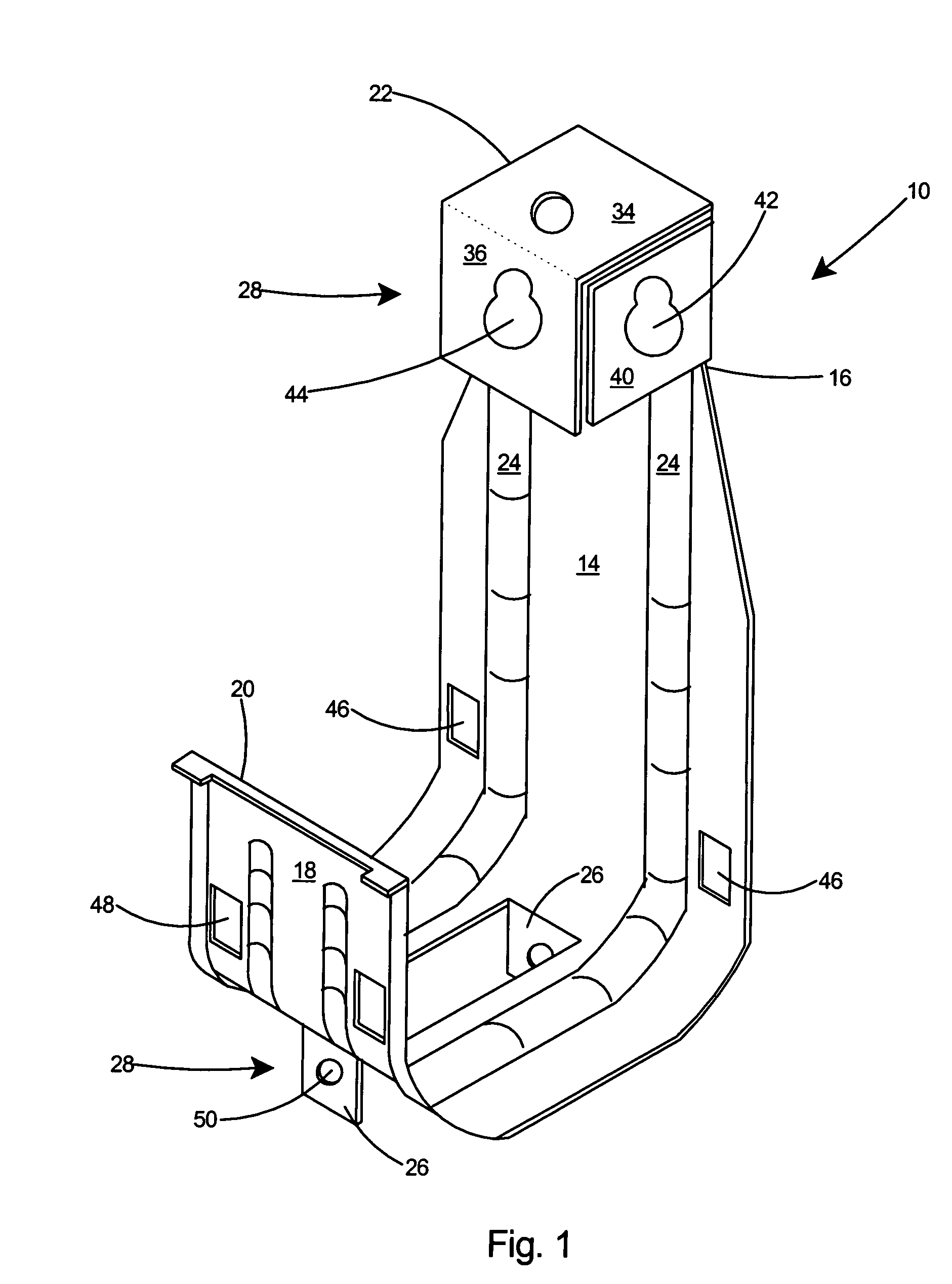
Figure 2 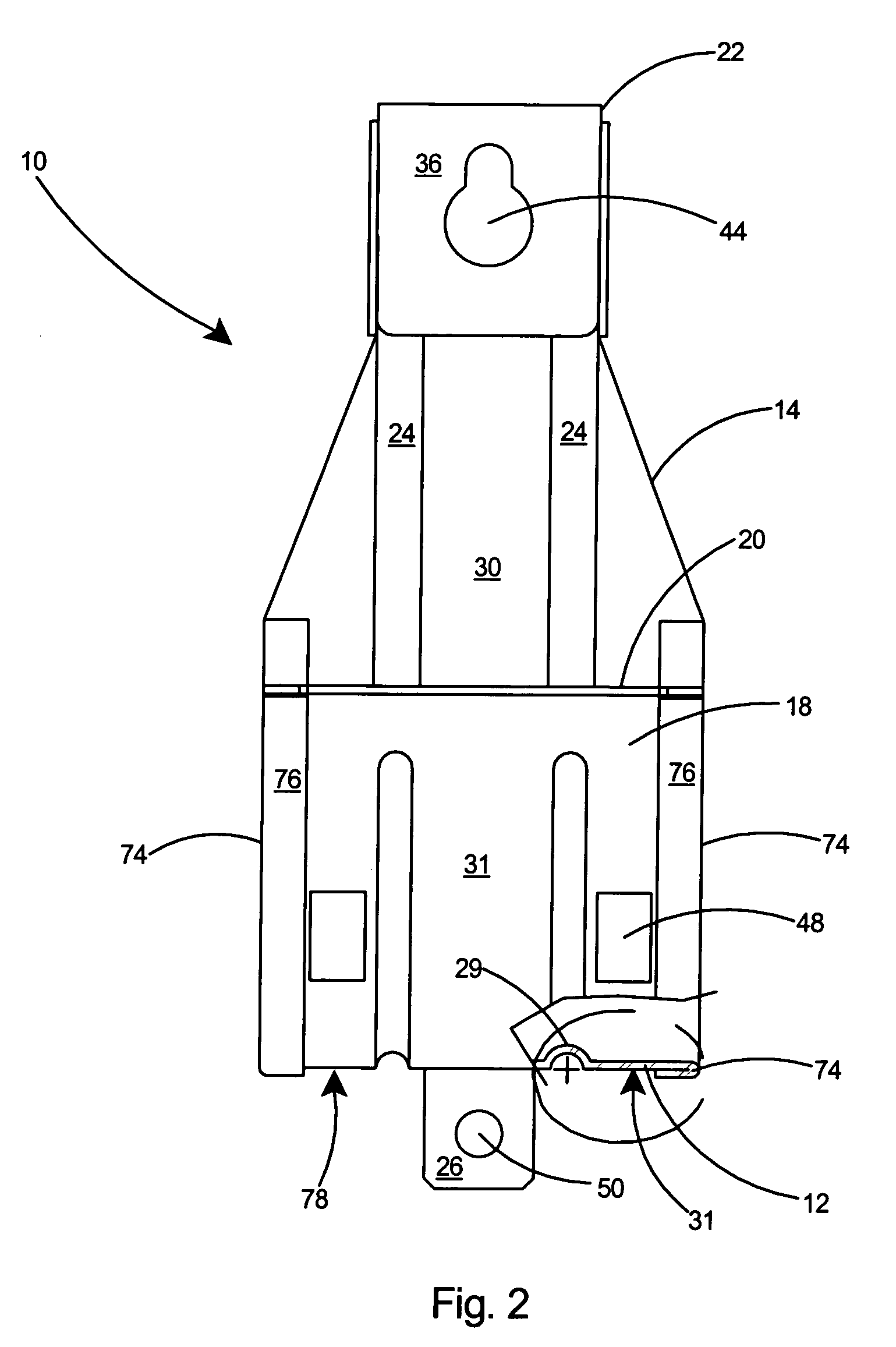
Figure 3
Abstract
Description
FIELD OF THE INVENTION
[0001] This invention relates to cable supports for communications cables rated for high data transmission rates and specifically to a cable support with improved stiffness, an improved cable retaining arrangement, and the capability of being ganged together with additional like cable supports for supporting several bundles of cable.BACKGROUND OF THE INVENTION
[0002] It is common to use high performance electrical telecommunication transmission cable to connect computers, servers, printers, faxes, and other electronic equipment. Unshielded twisted pair (UTP) cable has been developed to meet the high data transmission speeds needed in modern Local Area Networks (LAN). Many LANs today use Category 5 cable, the performance requirements of which are defined by the Electronic Industries Association (EIA) standard TSB-36 for UTP cable.
[0003] As data transmission rates increase, to connect various pieces of electronic equipment, it frequently is necessary to route high sp...
Examples
Embodiment Construction
[0027]With reference to FIG. 1, there is shown a preferred embodiment of a cable support 10 according to the present invention. The cable support 10 includes a cable tray 12 and a rear wall 14 that extends vertically from the cable tray 12 to a top end 16. A front wall 18 extends vertically from the cable tray 12 to a top end 20. A box-shaped mounting assembly 22 projects substantially forward from the top end 16 of the rear wall 14. One or more stiffeners 24 extend along the rear wall 14, the cable tray 12, and the front wall 18. Two or more receiving tabs 26 extend downwardly from the cable tray 12. A fastening arrangement 28 is included in the box-shaped mounting assembly 22 and the receiving tabs 26 to enable two or more of the cable supports 10 to be joined together by aligning the receiving tabs 26 with the box-shaped mounting assembly 22 and fastening with the fastening arrangement 28.
[0028]Referring to FIG. 2, as shown in the cutaway portion of the cable support 10 at the bo...