
Inductive magnetic position sensor
a position sensor and magnetic field technology, applied in the field of magnetic field, can solve the problems of inability to meet the needs of many lower-cost applications, large electrical current consumption of magnetostrictive sensors, and expensive devices, etc., and achieve the effects of small size, large measurement area, and low cos
Patent Information
- Authority / Receiving Office
- US · United States
- Patent Type
- Patents(United States)
- Current Assignee / Owner
- Publication Date
- 2010-10-12
- Estimated Expiration
- Not applicable · inactive patent
Smart Images
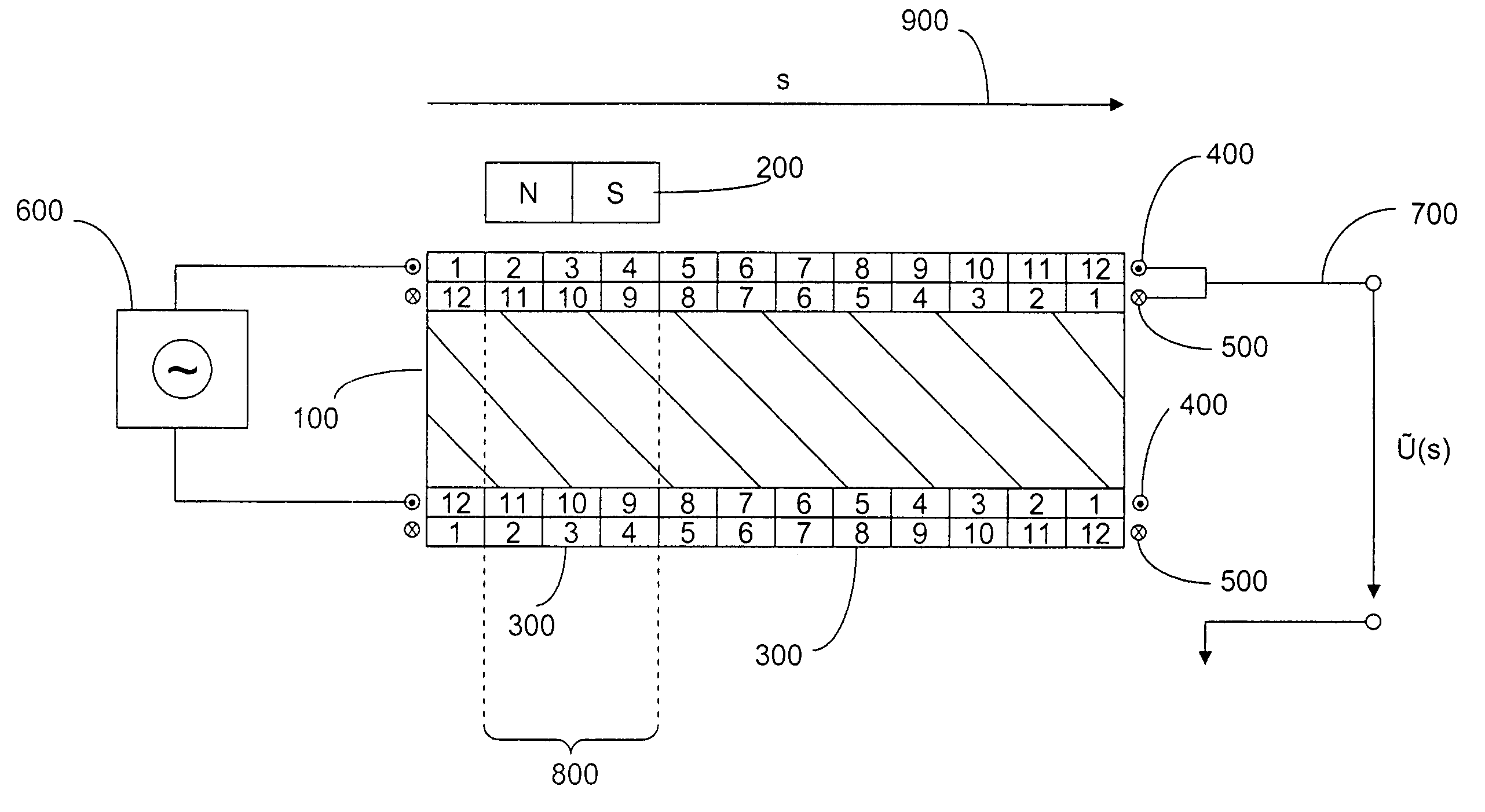
Figure 1 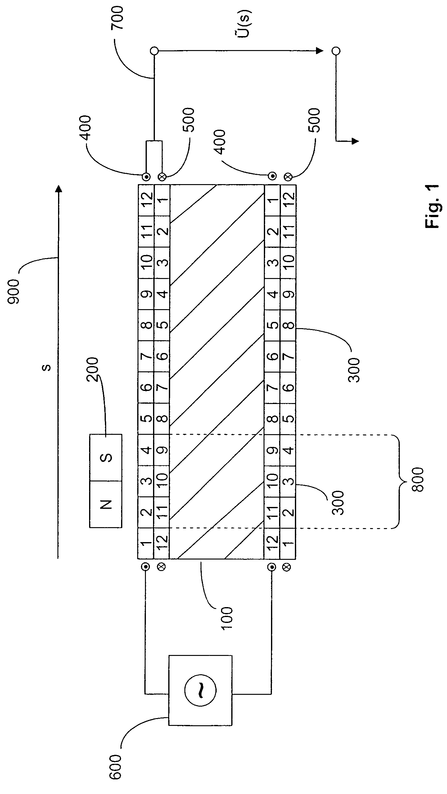
Figure 2
Abstract
Description
CROSS-REFERENCES TO RELATED APPLICATIONS
[0001] This application claims the priority of German Application No. 10 2006 061 771.1, filed Dec. 28, 2006, the disclosure of which is incorporated herein by reference.BACKGROUND OF THE INVENTION
[0002] The present invention concerns magnetic motion sensors which generate output signals that have linear characteristics and which include a coil that surrounds a ferromagnetic core and at least one permanent magnet that can be moved in the longitudinal direction of the coil and which causes a magnetic saturation along a zone that is parallel to the ferromagnetic core.
[0003] Motion sensors are used, for example, for monitoring the piston travel in hydraulic or automatic systems. Sensors which function according to the magnetostrictive principle are known, but they have their disadvantages. They require extensive electronics to process the output, which renders the devices costly and not suitable for many lower cost applications. Such sensors further...
Examples
Embodiment Construction
[0018]First and second winding layers 400, 500 surround a ferromagnetic core 100. The winding layers are divided into segments 300 of equal widths. The winding density within any given segment 300 is constant, and the winding density changes linearly from segment to segment over the path length 900. In the inner winding width 500, the respective winding densities decrease over the path length 900 as shown in the drawing by segments 12:11:10 . . . :1.
[0019]In the outer winding layer 400, the respective winding densities increase over the path length 900 as shown in the drawing by segments 1:2:3:4 . . . :12.
[0020]The length of segment 300 preferably is approximately one-third of the longitudinal dimension of magnet 200 that serves as a position indicator.
[0021]The outer winding 400 is wound about ferromagnetic core 100 in the opposite direction to the windings of inner winding layer 500.
[0022]At one end of the sensor, the two windings 400, 500 are electrically connected in series. Bot...