
Heating cooker
a technology for cooking and cooking surfaces, applied in the field of cooking cookers, can solve the problems of difficult viewing angle of displayed contents, and achieve the effects of wider visible angle, higher luminance, and easy viewing of displayed contents
Patent Information
- Authority / Receiving Office
- US · United States
- Patent Type
- Patents(United States)
- Current Assignee / Owner
- Publication Date
- 2011-12-06
- Estimated Expiration
- Not applicable · inactive patent
Smart Images
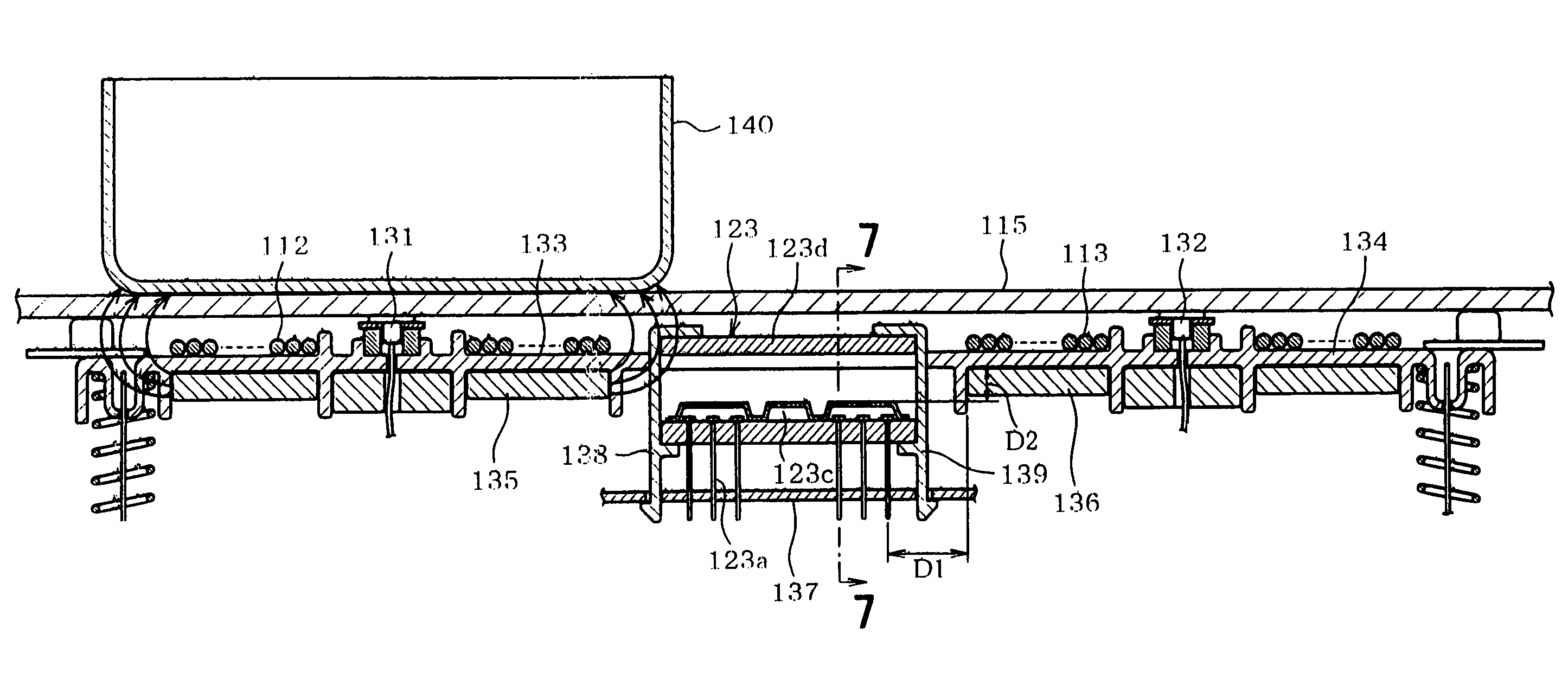
Figure 1 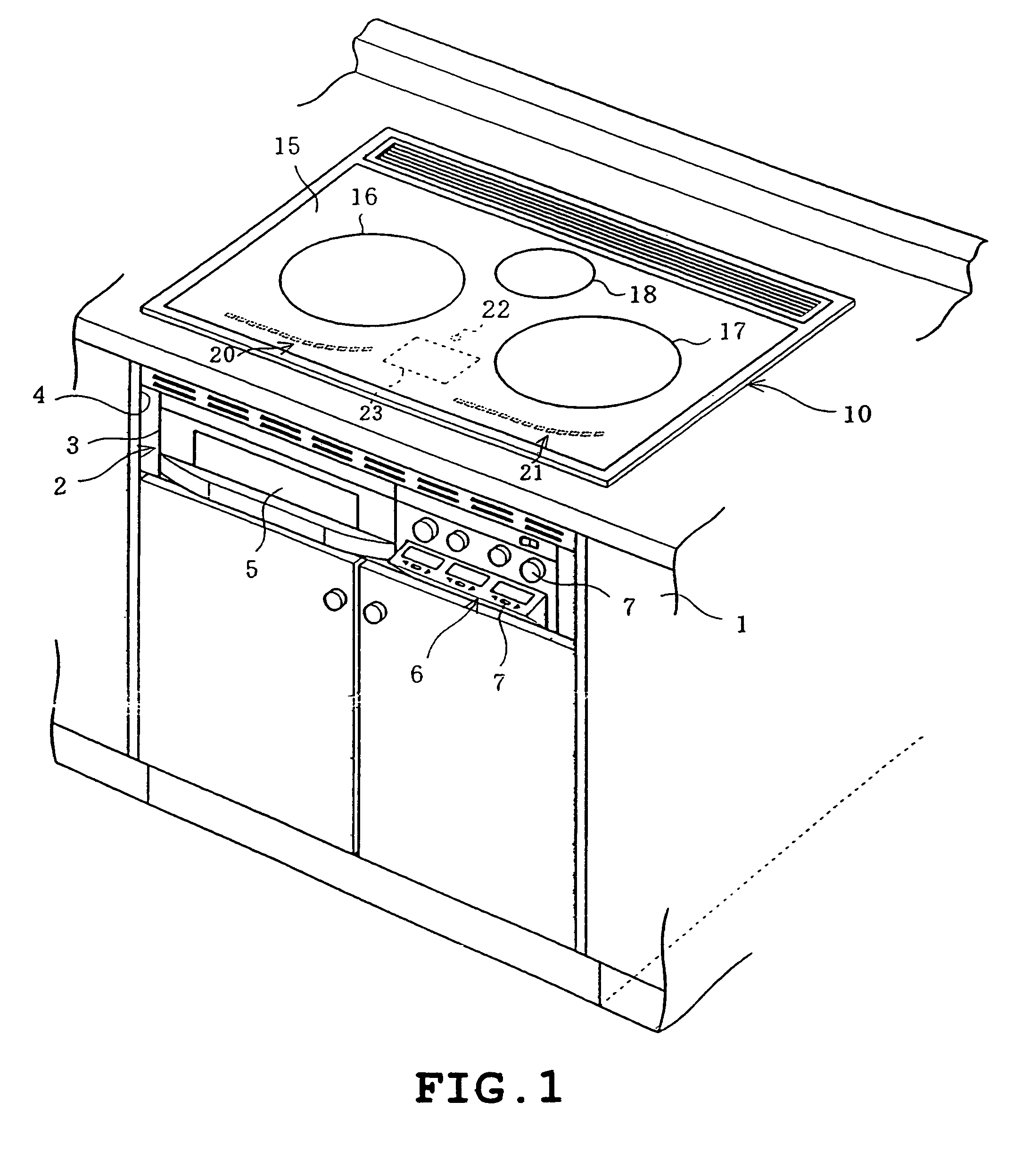
Figure 2 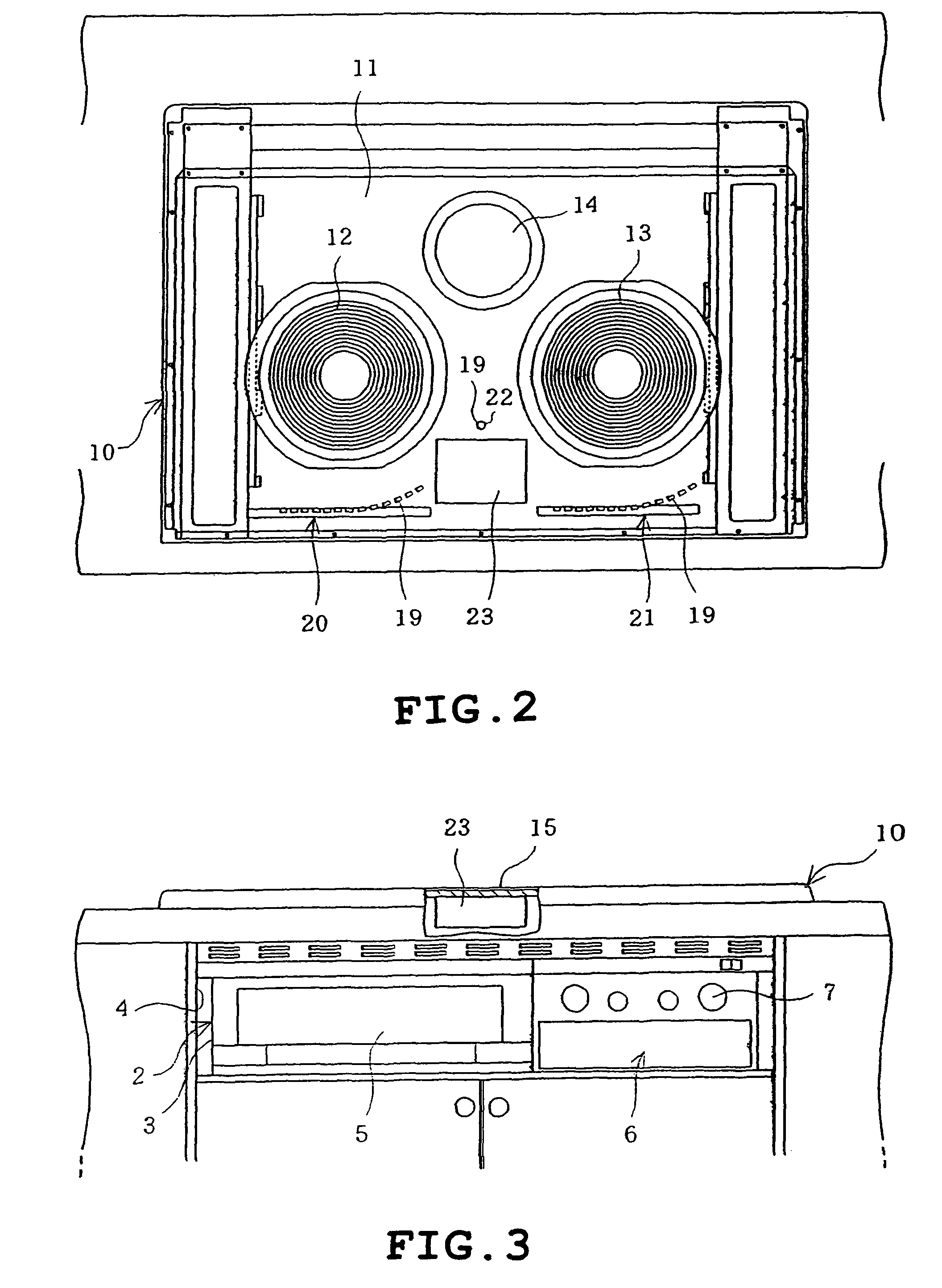
Figure 3
Abstract
Description
[0001] This application is a continuation of PCT / JP2005 / 007080, filed Apr. 12, 2005, which claims the benefit of priority of Japanese Application No. 2004-139818, filed May 10, 2004 and Japanese Application No. 2004-179958, filed Jun. 17, 2004, the contents of all which are incorporated herein by reference.TECHNICAL FIELD
[0002] The present invention relates to a heating cooker constructed to heat a heated object placed on a top plate by a heating unit provided below the top plate.BACKGROUND ART
[0003] As this type of heating cooker, for example, an induction heating cooker is known in which a liquid crystal display is provided below the top plate and a backlight is provided in the rear of the liquid crystal display so that on-off state of a heating coil serving as a heating unit, an input power level and the like are displayed by the liquid crystal display (see patent documents 1 and 2, for example). In this construction, a portion of the top plate corresponding to the liquid crystal di...
Examples
first embodiment
[0024]FIGS. 1 to 5 illustrate the invention. Firstly, FIG. 1 shows a kitchen cabinet in which a heating cooker 2 is built. In FIG. 1, a body 3 of the heating cooker 2 is housed in a housing 4 provided in the cabinet 1. A roaster 5 is provided in the left of the body 3 whereas an operating portion 6 is provided in the right of the body 3. The operating portion 6 is provided with a plurality of switches 7.
[0025]An upper heating unit 10 as shown in FIG. 2 is provided on the top of the body 3. The upper heating unit 10 includes a rectangular box-shaped upper case 11 with an upper opening, left and right heating coils 12 and 13 both for induction heating disposed left and right in the upper case 11 and a central heater 14 comprising a radiant heater, for example, located at a central rear side. The upper heating unit 10 has an upper opening closed by a top plate 15 which is made from heat-resistant glass and disposed to cover the heating coils 12 and 13 and the heater 14 from above.
[0026...
second embodiment
[0040]FIGS. 6 to 11 illustrate the invention. Firstly, FIG. 9 is a perspective view showing an appearance of the heating cooker 102 built in the cabinet 101 of the kitchen. FIG. 10 is a plan view of the major part of the heating cooker 102 with the top plate being removed. The body 103 of the heating cooker 102 is housed in a housing 104 provided in the cabinet 101. A roaster 105 is provided in the left of the body 103 whereas an operating portion 106 is provided in the right of the body 103. The operating portion 106 is provided with a plurality of switches 107.
[0041]An upper heating unit 110 as shown in FIG. 10 is provided on the top of the body 103. The upper heating unit 110 includes a rectangular box-shaped upper case 111 with an upper opening, left and right heating coils 112 and 113 both for induction heating disposed left and right in the upper case 111 and a central heater 114 comprising a radiant heater, for example, located at a central rear side. The upper heating unit 1...