
Collecting main for tubular cracking furnaces
a technology for collecting mains and cracking furnaces, which is applied in the direction of liquid spraying apparatus, lighting and heating apparatus, mixing methods, etc., to achieve the effects of reducing pressure loss, reducing creep flows, and reducing pressure loss
Patent Information
- Authority / Receiving Office
- US · United States
- Patent Type
- Patents(United States)
- Current Assignee / Owner
- Publication Date
- 2012-08-07
Smart Images
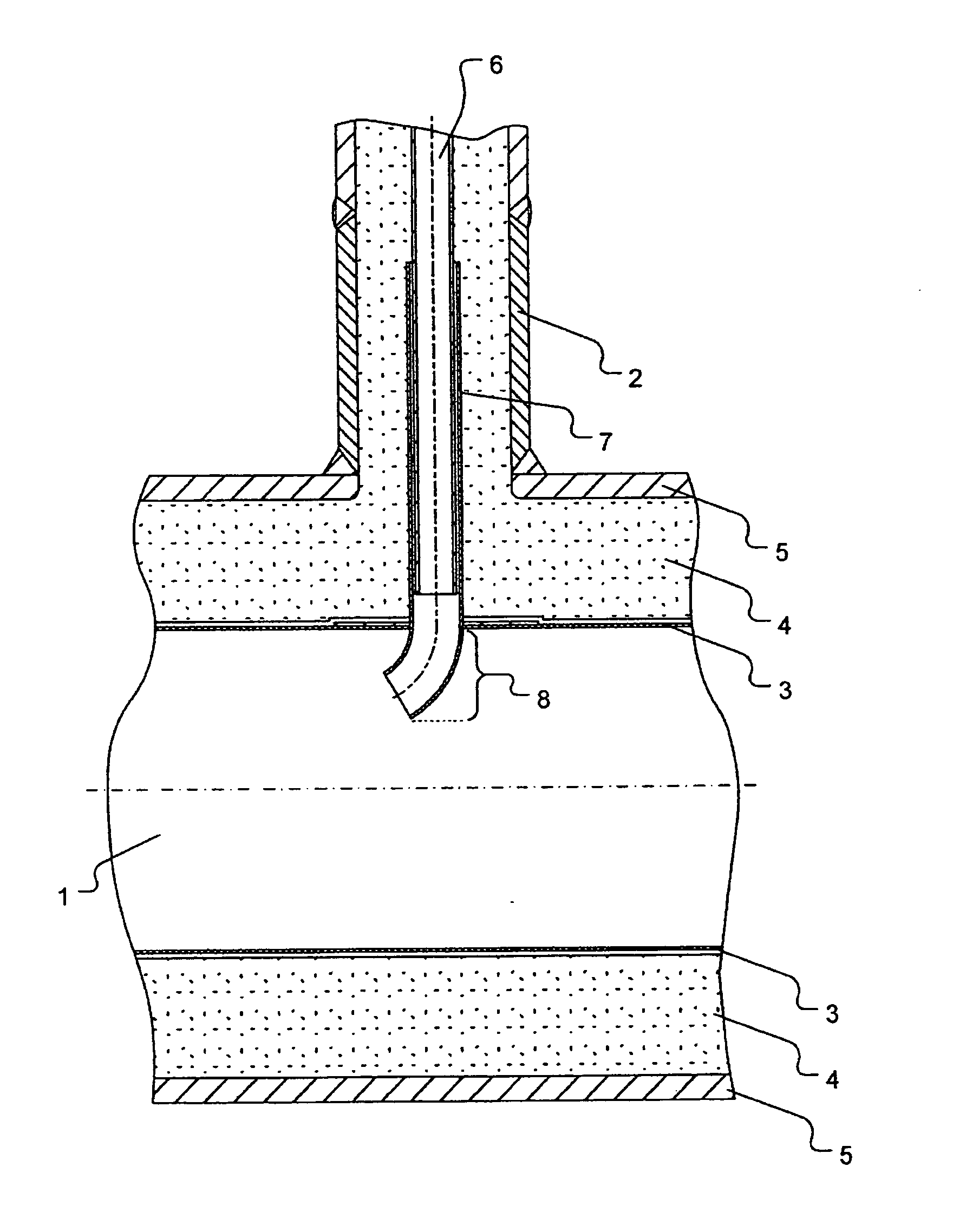
Figure 1 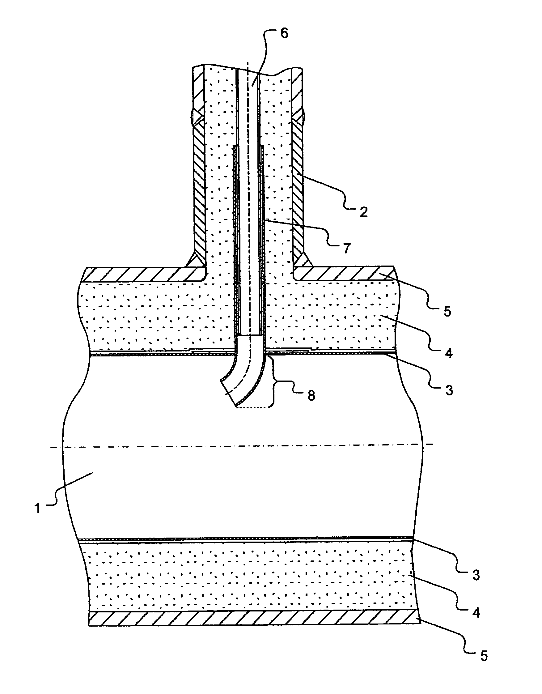
Figure 2
Abstract
Description
BACKGROUND OF THE INVENTION
[0001] The invention relates to a collecting main for the discharge of hot process gases from tubular cracking furnaces as frequently used in natural gas reforming plants for the production of synthesis gas. Such collecting main is always provided with several nozzles via which the process gas tubes of the tubular cracking furnace can be connected to the collecting main. In the area of the nozzles, the process gas tubes usually run in guide sleeves. The gas outlets of the guide sleeves or process gas tubes end in the collecting main and extend into it. Under proper operating conditions the reaction gas is introduced into the collecting main via these gas outlets, the present invention providing at least part of the outlets in the form of pipe bends. Furthermore, the invention relates to the use of such collecting mains in a tubular cracking furnace.
[0002] A plurality of tubular cracking furnaces is known which are used for the indirect heating of crackable f...
Examples
Embodiment Construction
[0021]Nozzle 2 is arranged above collecting main 1. Collecting main 1 consists of three layers. The first layer is made up by metal inner tube 3, the second layer by insulation layer 4 which is made of refractory concrete, and the third outer layer which consists of the outer or jacket tube 5. Nozzles 2 (in this example there is only one nozzle) are arranged above collecting main 1. In the area of nozzle 2, process gas tube 6 from the furnace chamber, which is not shown, runs in a guide sleeve 7. In the example shown process gas tube 6 ends in the area of insulation layer 4 in guide sleeve 7. At its free end, guide sleeve 7 is shaped as a bend 8, the outlet opening of which points into the direction of the main flow of collecting main 1.
[0022]
List of references used1Collecting main2Nozzle3Inner tube4Insulation layer5Outer tube6Process gas tube7Guide sleeve8Pipe bend