
Endoscope objective optical system
a technology of optical system and endoscope, which is applied in the field of endoscope objective optical system, can solve the problems of difficult configuration and difficult dimension, and achieve the effect of wide field angle reduced diameter of endoscope insertion portion
Patent Information
- Authority / Receiving Office
- US · United States
- Patent Type
- Patents(United States)
- Current Assignee / Owner
- Publication Date
- 2014-07-22
Smart Images
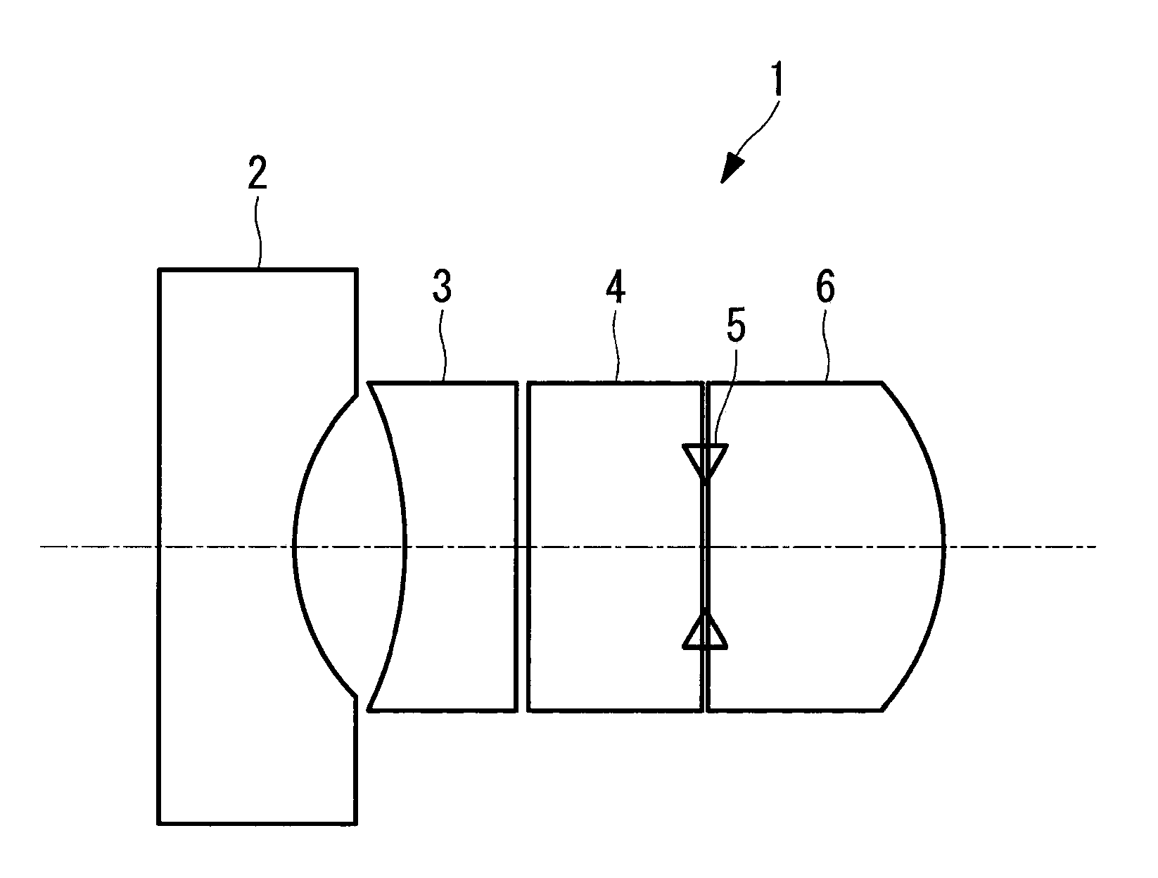
Figure 1 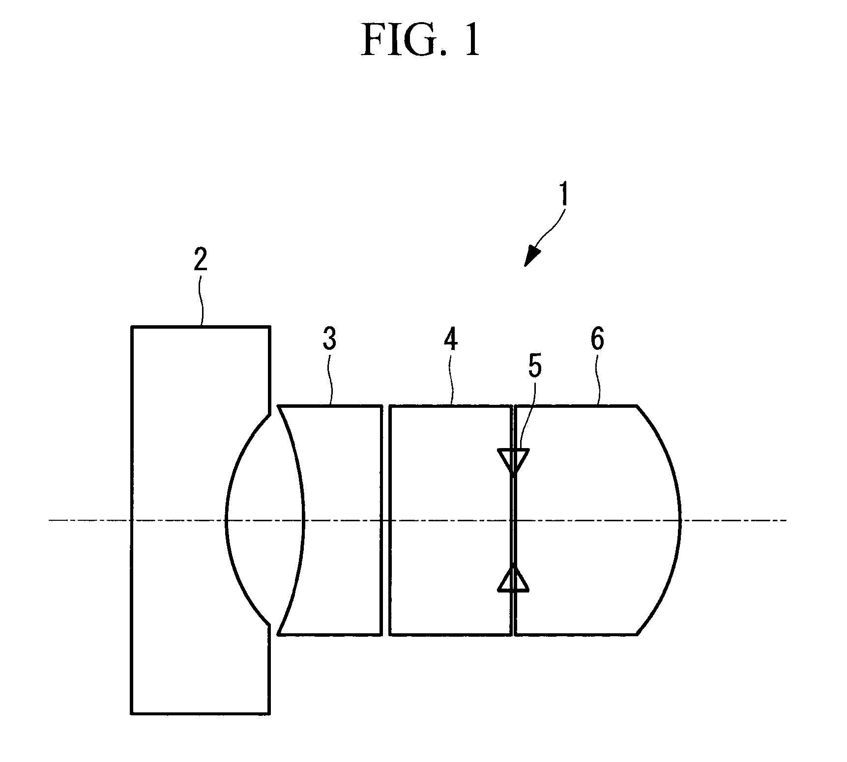
Figure 2 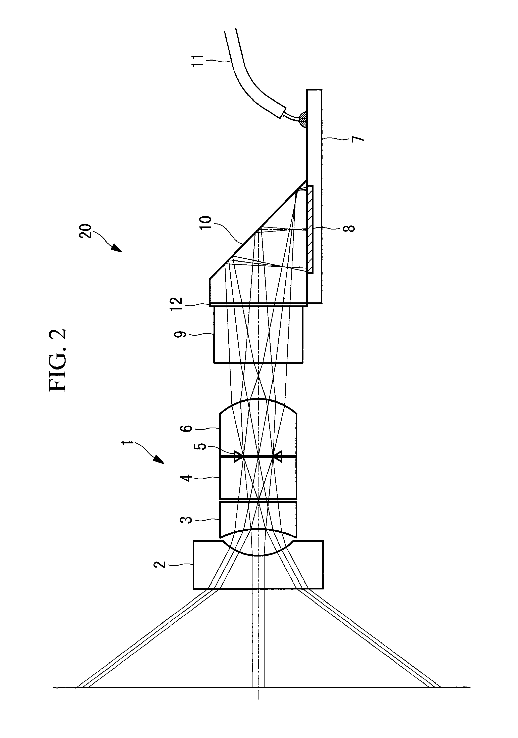
Figure 3
Abstract
Description
TECHNICAL FIELD
[0001] The present invention relates to an endoscope objective optical system.BACKGROUND ART
[0002] Conventionally, in order to obtain a lens system suitable for use of a solid-state imaging element, it is known to use an objective optical system which has a long back focus and a small size and which provides improvements in optical performance, such as an improvement in color reproducibility and a satisfactory correction of the image field curvature (see, for example, PTL 1).
[0003] The objective optical system disclosed in PTL 1 is used for forming an object image on a solid-state imaging element arranged on a linear optical axis. Therefore, a prism, and the like, which bends the optical axis, does not need to be arranged between the objective optical system and the solid-state imaging element, and hence a certain length of back focus is sufficient for the formation of the object image.CITATION LISTPatent Literature
[0004] {PTL 1} Japanese Unexamined Patent Application, Pu...
Examples
examples
[0039]Next, examples of the endoscope objective optical system 1 according to the above-described embodiment will be described below.
first example
[0040]FIG. 4 shows a lens array of an imaging optical system 20 including the endoscope objective optical system 1, according to a first example of the present embodiment, and Table 1 shows lens data. The lens data of Table 1 are normalized so that the focal length of the entire system is substantially equal to 1.
[0041]In the present example, the field angle is set to 108°.
[0042]
TABLE 1Surface numberrdnνObject∞56.5771∞0.65063091.768271.7921.0014060.48137013−2.9448120.62234261.88299740.7651074∞0.0575∞0.8486491.5211366.56∞0STO∞0.02828838∞09∞1.1315321.88299740.76510710−1.3069190.735855111∞1.1315321.5163364.14202212∞0.05657661.5164.1413∞2.4808841.6106150.214∞0
[0043]Further, in the present example, the specification values of the lenses are as follows.
[0044]fab=−0.849
[0045]f=0.988
[0046]fa=−3.335
[0047]fb=−1.304
[0048]fe=1.48
[0049]Na=1.7682
[0050]Nb=1.882997
second example
[0051]FIG. 5 shows a lens array of an imaging optical system 20 including the endoscope objective optical system 1, according to a second example of the present embodiment, and Table 2 shows lens data. The lens data of Table 2 are normalized so that the focal length of the entire system is substantially equal to 1.
[0052]In the present example, the field angle is set to 100°.
[0053]
TABLE 2Surface numberrdnνObject∞53.8551∞0.61932841.768271.7920.95322720.3733∞0.80781971.5211366.54∞0.1395−2.8031340.59240111.88299740.7651076∞0STO∞0.026927328∞09∞1.0770931.88299740.76510710−1.1497970.705495911∞1.0770931.5163364.14202212∞0.053854651.5164.1413∞2.3615261.6106150.214∞0
[0054]Further, in the present example, the specification values of the lenses are as follows.
[0055]fab=−0.722
[0056]f=0.989
[0057]fa=−1.241
[0058]fb=−3.175
[0059]fe=1.302
[0060]Na=1.7682
[0061]Nb=1.882997