
Compressible rotor for a fluid pump
Patent Information
- Authority / Receiving Office
- US · United States
- Current Assignee / Owner
- Publication Date
- 2016-08-16
Smart Images
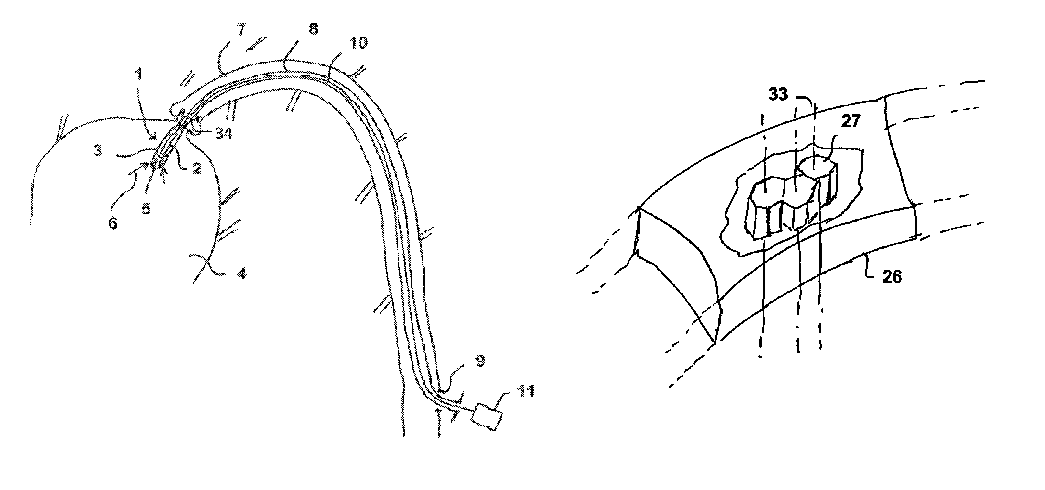
Figure 1 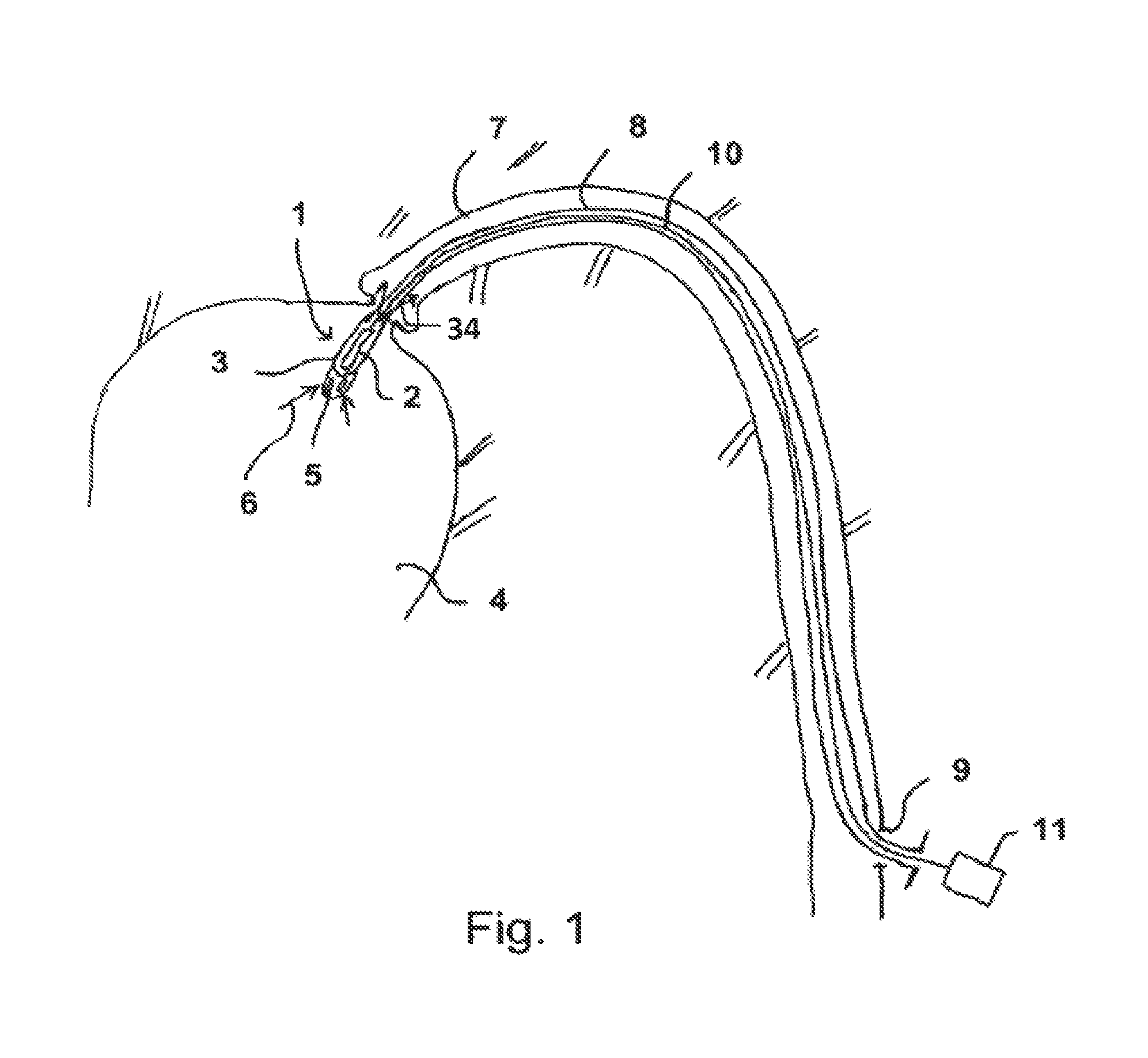
Figure 2 
Figure 3
Abstract
Description
BACKGROUND OF THE INVENTION
[0001] The present invention resides in the field of mechanical engineering, in particular precision engineering, and relates to rotors for fluid pumps.
[0002] Rotary pumps are common knowledge but these are constantly being improved, in particular for special applications. Thus axial pumps have become known which have a rotor conveying fluid in the axial direction in a housing, rotor and housing being deformable, advantageously compressible, in order to bring these before operation to a desired place of use which is difficult to access and in order to decompress and operate them there.
[0003] Such pumps are used for example in medicine in microconstruction form in order to be introduced into the body of a patient, for example via the bloodstream, and to be operated there either in a blood vessel or in a ventricle.
[0004] The pumps can be compressed such that they can be pushed through the blood vessel and then possibly decompressed in a larger body cavity in ord...
Examples
Embodiment Construction
[0059]FIG. 1 shows an axial pump having a rotor 2 and a housing 3 in the interior of a ventricle 4 in schematic view.
[0060]Within the ventricle 4, blood is suctioned in through openings 5 by the pump 1 as indicated by the arrows 6. The blood is expelled again in the direction of the arrows 34 within a blood vessel 7 and hence the pumping function of the heart is replaced or assisted.
[0061]The pump 1 is disposed at the distal end of a hollow catheter 8 which is inserted through the blood vessel 7 into the ventricle 4 and the proximal end thereof protrudes through a lock 9 out of the blood vessel and ultimately out of the body of the patient.
[0062]A drive shaft 10 which can be actuated, with a high speed of rotation, typically above 10,000 revolutions per minute, by means of a motor 11 which is disposed outside the body, is provided within the hollow catheter 8. In the pump 1, the rotor 2 is connected to the shaft 10 and rotates with the latter.
[0063]The pump 1 has a greater diameter ...