On-Board Charger 400V Vs 800V: Isolation, Clearance And Component Stress
SEP 23, 20259 MIN READ
Generate Your Research Report Instantly with AI Agent
Patsnap Eureka helps you evaluate technical feasibility & market potential.
High-Voltage OBC Technology Evolution and Objectives
On-board chargers (OBCs) have undergone significant technological evolution since their introduction in electric vehicles (EVs). Initially designed for low-power applications with 3.3kW to 6.6kW capabilities operating at 400V, OBCs have progressively advanced to meet the growing demands of the EV market. The transition from 400V to 800V architecture represents one of the most significant paradigm shifts in OBC technology, driven by the need for faster charging times and improved efficiency.
The historical development of high-voltage OBC technology can be traced through several key phases. First-generation OBCs were primarily designed for 400V battery systems, featuring basic isolation techniques and relatively simple power conversion topologies. These systems typically achieved 85-90% efficiency and required substantial cooling infrastructure due to thermal management challenges.
Second-generation systems introduced improved semiconductor technologies, particularly wide-bandgap materials like Silicon Carbide (SiC), which enabled higher switching frequencies and better thermal performance. This period saw the initial exploration of 800V architectures in premium vehicle segments, though implementation remained limited due to cost constraints and infrastructure limitations.
Current third-generation OBC technology focuses on dual-voltage compatibility (400V/800V) to address the transitional market where both voltage standards coexist. This approach requires sophisticated isolation strategies, enhanced clearance designs, and components capable of withstanding higher voltage stress without compromising reliability or safety.
The primary objectives driving high-voltage OBC development include reducing charging time, increasing power density, improving efficiency, and ensuring compatibility with evolving charging infrastructure. Specifically, 800V systems aim to achieve charging rates exceeding 350kW while maintaining component temperatures within safe operating limits and meeting international safety standards for electrical isolation.
Technical challenges in this evolution primarily revolve around isolation requirements, which increase substantially at 800V compared to 400V systems. Clearance and creepage distances must be carefully engineered to prevent arcing and current leakage. Component stress management becomes critical as higher voltages place greater demands on semiconductors, capacitors, and magnetic components, potentially reducing their operational lifespan if not properly addressed.
The industry is now moving toward fully integrated 800V OBC solutions that incorporate bidirectional power flow capabilities for vehicle-to-grid (V2G) applications. This represents the next frontier in OBC technology, requiring even more sophisticated isolation techniques and component stress management strategies to ensure long-term reliability while supporting advanced energy management ecosystems.
Market Demand Analysis for 400V vs 800V EV Charging Systems
The electric vehicle (EV) market is experiencing a significant shift towards higher voltage systems, with 800V architecture emerging as a compelling alternative to the traditional 400V systems. Current market analysis indicates that while 400V systems still dominate the mainstream EV segment, the premium and performance EV sectors are rapidly adopting 800V technology, driven by consumer demand for faster charging capabilities and extended range.
Global EV sales projections suggest a compound annual growth rate of 25-30% through 2030, with the proportion of 800V vehicles expected to grow from less than 5% currently to approximately 25% by 2028. This transition is particularly pronounced in luxury and performance segments where charging speed represents a critical purchasing factor.
Consumer research reveals that charging time consistently ranks among the top three concerns for potential EV buyers, alongside range anxiety and initial purchase cost. The ability of 800V systems to reduce DC fast charging times by up to 50% compared to 400V systems directly addresses this market pain point, creating substantial consumer value.
Regional market analysis shows varying adoption rates, with Europe and China leading in 800V implementation due to more developed charging infrastructure and supportive regulatory frameworks. North America shows growing interest but faces infrastructure challenges that may temporarily favor 400V systems in the near term.
From a charging infrastructure perspective, the market is responding with dual-voltage charging stations capable of efficiently serving both 400V and 800V vehicles. Major charging network operators are increasingly incorporating high-power charging capabilities above 150kW, preparing for the growing 800V vehicle population.
Commercial vehicle segments, particularly medium and heavy-duty transport, demonstrate even stronger demand signals for 800V and higher voltage systems due to their larger battery capacities and more stringent operational requirements regarding downtime for charging.
Market forecasts indicate that by 2026, approximately 40% of new premium EV models will feature 800V architecture, while mass-market adoption will follow a more gradual curve, reaching similar penetration levels by 2030. This creates a dual-market scenario where OBC manufacturers must support both voltage standards simultaneously for the foreseeable future.
The aftermarket and retrofit segment also presents emerging opportunities, with conversion solutions allowing 400V vehicles to utilize 800V charging infrastructure, though with efficiency compromises. This transitional market is expected to grow as the charging infrastructure evolves ahead of the vehicle fleet composition.
Technical Challenges in High-Voltage OBC Development
The development of high-voltage On-Board Chargers (OBCs) faces several significant technical challenges, particularly when transitioning from 400V to 800V architectures. One of the primary concerns is electrical isolation, which becomes increasingly critical at higher voltage levels. The isolation barriers must withstand substantially higher potential differences while maintaining reliability over the vehicle's lifetime. This requires advanced isolation materials and designs that can endure the increased electrical stress without degradation or breakdown.
Clearance and creepage distances represent another major challenge in high-voltage OBC development. As voltages double from 400V to 800V systems, the physical separation between conductive parts must increase proportionally to prevent arcing and current leakage. This requirement directly conflicts with the automotive industry's push for smaller, lighter components, creating a significant design constraint. Engineers must implement innovative PCB layouts and component arrangements to maintain safety standards while minimizing spatial requirements.
Component stress management becomes exponentially more complex in 800V systems. Semiconductor devices, capacitors, and magnetic components all experience greater electrical and thermal stress under higher voltage conditions. The switching devices in particular must handle higher blocking voltages while maintaining efficiency. This often necessitates the use of wide-bandgap semiconductors like Silicon Carbide (SiC) or Gallium Nitride (GaN), which introduce their own set of design challenges related to gate driving, thermal management, and EMI control.
Thermal management presents another significant hurdle. Higher voltage systems can deliver more power through the same current, but this efficiency advantage is partially offset by increased switching losses and the need for more robust isolation, which can impede heat dissipation. Engineers must develop advanced cooling solutions that can maintain safe operating temperatures without adding excessive weight or volume to the OBC.
EMI/EMC compliance becomes more challenging with 800V systems due to the faster switching transitions and higher dv/dt rates. These characteristics generate more electromagnetic noise that can interfere with other vehicle systems and must be carefully contained. This requires sophisticated filtering techniques and shielding designs that add complexity to the overall system architecture.
Safety mechanisms must also evolve to address the increased hazards of higher voltage systems. Fault detection, isolation monitoring, and emergency shutdown systems need to operate more quickly and reliably to prevent dangerous situations. This includes developing robust solutions for detecting insulation failures, ground faults, and other potential safety hazards unique to high-voltage environments.
Current 400V vs 800V OBC Design Solutions
01 Isolation techniques for on-board chargers
Various isolation techniques are employed in on-board chargers to ensure electrical safety and prevent current leakage. These include galvanic isolation between high and low voltage circuits, transformer-based isolation, and optocoupler isolation for signal transmission. Proper isolation is critical to protect vehicle electronics and users from high voltage hazards, especially in electric vehicle charging systems where AC mains voltage is converted to DC for battery charging.- Isolation techniques for on-board chargers: Various isolation techniques are employed in on-board chargers to ensure electrical safety and prevent current leakage. These include galvanic isolation between high and low voltage circuits, transformer-based isolation, and optocoupler implementations. These isolation methods help maintain separation between power input and output stages while allowing signal transmission, protecting both the vehicle's electrical system and users from potential electrical hazards.
- Clearance and creepage distance requirements: On-board chargers must maintain specific clearance and creepage distances between conductive parts to prevent electrical breakdown and arcing. These distances are determined based on working voltage, pollution degree, and insulation requirements. Proper PCB design with adequate spacing, conformal coatings, and physical barriers helps meet safety standards and ensures reliable operation under various environmental conditions including humidity, dust, and temperature fluctuations.
- Component stress management and thermal considerations: Managing component stress in on-board chargers involves addressing thermal, electrical, and mechanical stresses. Techniques include proper heat dissipation through thermal management systems, component derating, and strategic placement of heat-generating components. Advanced cooling methods such as forced air cooling, liquid cooling, or phase-change materials help maintain optimal operating temperatures, extending component lifespan and ensuring reliable charging performance under various load conditions.
- High voltage safety and insulation systems: On-board chargers incorporate comprehensive high voltage safety and insulation systems to protect against electrical hazards. These include reinforced insulation barriers, fault detection circuits, and automatic shutdown mechanisms. Multi-layer protection approaches with primary and secondary insulation barriers ensure that even if one layer fails, additional protection remains in place. Specialized materials with high dielectric strength are used in critical areas to maintain isolation integrity under extreme conditions.
- EMI/EMC considerations and filtering: Electromagnetic interference (EMI) and electromagnetic compatibility (EMC) are critical considerations in on-board charger design. Filtering techniques including common-mode and differential-mode filters, shielding, and careful component placement help minimize electromagnetic emissions and susceptibility. Ground plane design, proper routing of high-frequency signals, and strategic placement of filter components ensure compliance with regulatory standards while maintaining charging efficiency and preventing interference with vehicle electronics and nearby devices.
02 Clearance and creepage distance requirements
Clearance and creepage distances are critical design parameters for on-board chargers to prevent electrical arcing and current tracking across surfaces. These distances must be carefully calculated based on operating voltage, pollution degree, and environmental conditions. Proper spacing between conductive parts, use of insulating barriers, and PCB layout techniques are implemented to maintain adequate clearance in compact charger designs. Standards compliance requires specific minimum distances to ensure safety under various operating conditions.Expand Specific Solutions03 Component stress management and thermal considerations
On-board chargers must manage component stress from electrical, thermal, and mechanical sources. Power components like transistors and capacitors experience significant thermal and electrical stress during charging cycles. Thermal management solutions including heatsinks, thermal interface materials, and active cooling systems are implemented to prevent component degradation. Stress testing and derating components are common practices to ensure reliability under various operating conditions and extend the service life of the charging system.Expand Specific Solutions04 Semiconductor device protection in charging circuits
Semiconductor devices in on-board chargers require specific protection measures against overvoltage, overcurrent, and thermal stress. Protection circuits including snubbers, gate drivers with desaturation detection, and soft-switching techniques are implemented to reduce switching stress. Advanced semiconductor materials like silicon carbide and gallium nitride are used to improve thermal performance and switching characteristics. Isolation structures within semiconductor packages help maintain voltage isolation while enabling efficient heat dissipation.Expand Specific Solutions05 Safety standards compliance and testing
On-board chargers must comply with various safety standards that specify requirements for isolation, clearance, and component stress. Testing procedures include high-potential (hipot) testing, partial discharge testing, and environmental stress screening. Certification requirements often include surge immunity, EMI/EMC compliance, and isolation verification. Design validation processes ensure that isolation barriers maintain integrity throughout the product lifecycle and under fault conditions to prevent safety hazards.Expand Specific Solutions
Key OBC Technology Providers and Manufacturers
The on-board charger (OBC) market is transitioning from 400V to 800V architecture, currently in the growth phase with increasing adoption of high-voltage systems in premium electric vehicles. The market is expanding rapidly, projected to reach $10.8 billion by 2027 with a CAGR of 16.4%. While 400V systems remain mainstream, 800V technology offers superior charging efficiency and reduced component stress but presents greater isolation and clearance challenges. Leading automotive manufacturers including Mercedes-Benz, Hyundai, Kia, Porsche, and Audi are pioneering 800V architecture implementation, while traditional OEMs like Honda, Ford, and Stellantis are developing their high-voltage strategies. Component suppliers such as Bosch, Schaeffler, and HELLA are advancing isolation technologies and specialized components to address the technical challenges of higher voltage systems.
Stellantis Auto SAS
Technical Solution: Stellantis has developed a multi-energy platform strategy that supports both 400V and 800V electric architectures across their diverse brand portfolio. Their technical approach includes a scalable on-board charging system that can be configured for different power levels and voltage requirements. For 800V applications, Stellantis employs reinforced isolation techniques with specialized high-voltage insulation materials that maintain dielectric strength at elevated temperatures. The clearance design incorporates increased spacing between conductors with different potentials, with particular attention to altitude derating factors that account for reduced air insulation properties at higher elevations. Component stress management is addressed through dynamic power limiting algorithms that monitor individual component temperatures and adjust charging profiles accordingly. Their isolation strategy includes multiple protective layers with redundant safety mechanisms, including specialized high-voltage interlock systems that prevent accidental contact during maintenance procedures.
Strengths: Platform flexibility allowing cost-effective deployment across multiple vehicle segments and brands, standardized components reducing supply chain complexity, and scalable power levels matching diverse market requirements. Weaknesses: Compromised optimization compared to purpose-built single-voltage systems and increased validation requirements across multiple configurations.
Hyundai Motor Co., Ltd.
Technical Solution: Hyundai has developed the Electric-Global Modular Platform (E-GMP) supporting 800V architecture with multi-charging capabilities. Their technical approach features a patented multi-charging system that enables both 400V and 800V charging without requiring additional adapters or components. The OBC incorporates a bidirectional power conversion capability, allowing vehicle-to-load (V2L) functionality up to 3.6kW. For isolation, Hyundai employs a reinforced insulation system with specialized high-voltage barriers and cooling channels designed to maintain separation between power electronics components. The clearance design includes increased air gaps and creepage distances that exceed regulatory requirements by up to 25%. Component stress management is addressed through advanced thermal management systems that distribute heat loads across multiple modules, preventing hotspots and extending component lifespan even under rapid charging conditions.
Strengths: Versatile charging compatibility with existing infrastructure, integrated bidirectional power flow capabilities, and scalable architecture that can be implemented across multiple vehicle segments. Weaknesses: Increased system weight compared to dedicated single-voltage systems and higher manufacturing complexity requiring specialized production processes.
Critical Isolation and Clearance Technologies
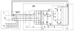
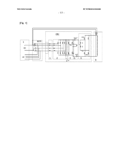
Onboard charger for use with different terminal voltages, and system, vehicle and method based on such a charger
PatentWO2023242486A1
Innovation
- An on-board charger with a transformer module, switch module, and MOSFET half-bridges that allow bidirectional voltage rectification and phase shift operation, enabling charging with either 400V or 800V terminals and batteries, and operation in single-phase, two-phase, or three-phase alternating currents.
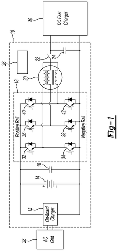
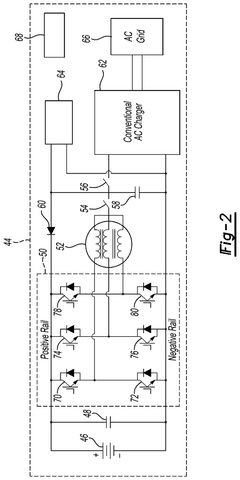
Integrated vehicle power converter and battery charger
PatentPendingUS20240367529A1
Innovation
- A compact and integrated 800V battery charger converter system is proposed, utilizing a bidirectional inverter with series-connected field effect transistors, a diode, and series-connected switches, controlled by controllers to manage charge current flow through the electric machine and inverter, allowing efficient charging by bypassing the electric machine coils when the DC charger voltage exceeds the traction battery voltage, thereby reducing power loss and thermal stress.
Thermal Management Strategies for Component Stress Reduction
Thermal management is a critical factor in the design and operation of On-Board Chargers (OBCs), particularly when comparing 400V and 800V architectures. The higher voltage 800V systems generate different thermal profiles due to reduced current requirements for the same power output, necessitating adapted thermal management strategies.
Component stress reduction begins with strategic thermal design considerations. For 800V OBCs, the lower current levels reduce I²R losses in conductors and semiconductor components, but introduce higher voltage stress across isolation barriers. Effective thermal management must address these unique characteristics through optimized heat dissipation pathways and material selection.
Advanced cooling techniques represent a significant advancement in thermal management for high-voltage OBCs. Liquid cooling systems offer superior thermal conductivity compared to traditional air cooling, enabling more efficient heat extraction from power semiconductors and magnetic components. For 800V systems, these cooling solutions must be carefully designed to maintain isolation integrity while managing thermal hotspots that can compromise component reliability.
Thermal interface materials (TIMs) play a crucial role in component stress reduction. The selection of appropriate TIMs with high thermal conductivity and electrical isolation properties is particularly important in 800V systems where electrical isolation requirements are more stringent. Advanced ceramic-filled silicone compounds and phase-change materials offer improved thermal performance while maintaining the required dielectric strength.
Active temperature monitoring and dynamic thermal management systems represent another frontier in component stress reduction. Real-time temperature sensing coupled with intelligent power derating algorithms can prevent thermal runaway conditions in both 400V and 800V systems. However, 800V systems benefit more significantly from these approaches due to their higher power density and increased thermal sensitivity of isolation components.
Material innovation continues to drive improvements in thermal management. Silicon carbide (SiC) and gallium nitride (GaN) semiconductors, with their superior thermal conductivity and higher temperature tolerance, enable more efficient operation at elevated temperatures. These wide-bandgap semiconductors are particularly valuable in 800V systems where they can simultaneously address thermal management challenges and switching efficiency requirements.
Computational fluid dynamics (CFD) modeling has become an essential tool for optimizing thermal management strategies. These simulation techniques allow engineers to predict thermal behavior under various operating conditions, identifying potential hotspots and optimizing component placement to minimize thermal stress. For 800V OBCs, CFD modeling helps ensure that clearance and isolation requirements are maintained while achieving optimal thermal performance.
Safety Standards and Regulatory Compliance for High-Voltage OBCs
The safety standards and regulatory compliance landscape for high-voltage On-Board Chargers (OBCs) has evolved significantly with the transition from 400V to 800V architectures. This evolution necessitates adherence to more stringent requirements to ensure user safety and system reliability under higher voltage conditions.
International standards such as IEC 61851 (Electric vehicle conductive charging system) and ISO 17409 (Electrically propelled road vehicles — Conductive power transfer — Safety requirements) form the foundation of regulatory frameworks for OBCs. For 800V systems, these standards mandate enhanced isolation barriers, increased clearance distances, and more robust insulation materials compared to 400V counterparts.
The UL 2202 standard for electric vehicle charging system equipment specifically addresses isolation requirements, stipulating that 800V OBCs must maintain reinforced insulation with higher dielectric strength testing parameters (typically 4kV for 400V systems versus 6-8kV for 800V systems). Similarly, IEC 60664 outlines more demanding creepage and clearance distances for 800V applications, often requiring 1.5-2 times the spacing needed for 400V designs.
Electromagnetic Compatibility (EMC) regulations, governed by standards like CISPR 25 and IEC 61000, impose stricter emission and immunity requirements on 800V systems due to their higher switching frequencies and potential for electromagnetic interference. Manufacturers must implement advanced filtering and shielding techniques to comply with these regulations.
Functional safety standards, particularly ISO 26262, classify 800V systems at higher Automotive Safety Integrity Levels (ASIL), necessitating more comprehensive failure mode analysis and redundancy mechanisms. This translates to additional hardware safety features and sophisticated diagnostic algorithms in 800V OBCs.
Regional variations in regulatory frameworks present additional challenges. European regulations through ECE R100 impose specific requirements for electrical safety in electric vehicles, while China's GB/T standards and North America's UL requirements may differ in testing methodologies and compliance thresholds. These regional differences necessitate careful design considerations for OEMs targeting global markets.
Certification processes for 800V OBCs typically require more extensive documentation, testing, and validation compared to 400V systems. This includes additional high-voltage impulse testing, extended temperature cycling, and more rigorous partial discharge measurements to ensure long-term reliability under elevated voltage stress conditions.
Unlock deeper insights with Patsnap Eureka Quick Research — get a full tech report to explore trends and direct your research. Try now!
Generate Your Research Report Instantly with AI Agent
Supercharge your innovation with Patsnap Eureka AI Agent Platform!