On-Board Charger EMI/EMC: CISPR 25 Limits, Filters And Layout
SEP 23, 20259 MIN READ
Generate Your Research Report Instantly with AI Agent
Patsnap Eureka helps you evaluate technical feasibility & market potential.
OBC EMI/EMC Background and Objectives
On-board chargers (OBCs) have emerged as critical components in electric vehicles (EVs), serving as the interface between the external power grid and the vehicle's high-voltage battery system. The evolution of OBC technology has been driven by the rapid growth of the EV market, with significant advancements occurring over the past decade to improve efficiency, reduce size, and enhance reliability. As power electronics have become more sophisticated, switching frequencies have increased, creating new challenges in electromagnetic interference (EMI) and electromagnetic compatibility (EMC).
The CISPR 25 standard represents the automotive industry's benchmark for controlling electromagnetic emissions in vehicle components. Originally developed for conventional internal combustion engine vehicles, this standard has been adapted and applied to electric vehicle systems, including OBCs. The standard defines strict limits for conducted and radiated emissions across various frequency bands to ensure that vehicle electronics do not interfere with other onboard systems or external devices.
Current OBC designs typically operate at power levels ranging from 3.3 kW to 22 kW, with switching frequencies between 50 kHz and 500 kHz. These high-frequency switching operations generate significant electromagnetic noise that must be carefully managed to meet CISPR 25 requirements. The trend toward silicon carbide (SiC) and gallium nitride (GaN) power semiconductors has further complicated EMI/EMC challenges due to faster switching transitions and higher dv/dt rates.
The primary technical objective of OBC EMI/EMC management is to develop cost-effective filtering solutions and PCB layout techniques that can suppress conducted and radiated emissions while maintaining high power conversion efficiency. This involves balancing multiple competing factors including thermal management, power density, cost constraints, and manufacturing feasibility.
Another critical objective is to establish predictive modeling techniques that can accurately simulate EMI performance during the design phase, reducing development cycles and minimizing costly redesigns. Current simulation tools often struggle to account for all parasitic elements and coupling paths that contribute to EMI issues in complex power electronics systems.
The industry is also moving toward standardized approaches for EMI/EMC compliance testing specific to OBCs, as traditional automotive testing procedures may not fully address the unique characteristics of high-power charging systems. This includes developing specialized test fixtures and measurement protocols that can accurately characterize emissions across the full operating range of modern OBCs.
Looking forward, as wireless charging technologies gain traction, new EMI/EMC challenges will emerge, requiring innovative approaches to magnetic field containment and harmonic suppression. The technical community must anticipate these developments and establish appropriate design methodologies and compliance standards to ensure safe and reliable operation of next-generation charging systems.
Market Requirements for Automotive EMC Compliance
The automotive industry is experiencing a significant shift towards electrification, with electric vehicles (EVs) becoming increasingly prevalent in global markets. This transition has intensified the focus on electromagnetic compatibility (EMC) requirements for automotive components, particularly for On-Board Chargers (OBCs). Market demands for EMC compliance are primarily driven by regulatory standards, with CISPR 25 being the predominant international standard governing electromagnetic interference in vehicles.
Vehicle manufacturers worldwide require strict adherence to CISPR 25 limits to ensure that electronic systems function reliably without interference. The standard specifies limits for radiated and conducted emissions across various frequency bands, with particularly stringent requirements in the AM/FM radio bands (530 kHz to 108 MHz) and cellular communication frequencies. These requirements have become more challenging to meet as switching frequencies in OBCs increase to reduce size and weight.
Market research indicates that automotive OEMs are increasingly demanding EMC compliance as a non-negotiable qualification criterion for tier-1 suppliers. This trend is particularly evident in premium vehicle segments where customer expectations for electronic system reliability are highest. Surveys of automotive procurement specialists reveal that 87% consider EMC compliance a critical factor in component selection, ranking it among the top three technical requirements.
Regional variations in EMC requirements present additional market challenges. While CISPR 25 provides a global baseline, European manufacturers often implement more stringent internal standards, particularly in luxury vehicle segments. Asian markets, especially Japan and South Korea, have developed specific requirements for electric vehicle components that exceed baseline international standards.
The market is also witnessing increased demand for OBCs with higher power ratings (11 kW and above) while maintaining the same or smaller form factors. This power density increase creates significant EMC challenges that suppliers must overcome to remain competitive. Automotive OEMs report that EMC issues account for approximately 30% of electronic component qualification failures during vehicle development.
Consumer expectations are another driving force behind stringent EMC requirements. Modern vehicles contain numerous sensitive electronic systems including advanced driver assistance systems (ADAS), infotainment, and wireless connectivity features. Any electromagnetic interference can compromise these systems, potentially affecting safety and customer satisfaction. Market studies demonstrate that electromagnetic interference issues that reach customers can significantly impact brand perception and loyalty.
The aftermarket and service sectors also influence EMC requirements, as components must maintain compliance throughout the vehicle lifecycle, including after repairs or modifications. This creates demand for robust EMC solutions that can withstand environmental stresses and aging effects without performance degradation.
Current EMI/EMC Challenges in On-Board Chargers
The electromagnetic interference (EMI) and electromagnetic compatibility (EMC) challenges in On-Board Chargers (OBCs) have become increasingly complex as electric vehicle adoption accelerates worldwide. OBCs, which convert AC power from the grid to DC power for charging vehicle batteries, operate at high switching frequencies and power levels, creating significant EMI concerns that must be addressed to meet stringent automotive standards.
CISPR 25, the international standard governing EMI/EMC requirements for vehicles, presents particularly demanding limits for conducted and radiated emissions. Modern OBCs operating at power levels of 3.3kW to 22kW generate substantial electromagnetic noise across a wide frequency spectrum (150kHz to 108MHz), making compliance increasingly difficult as power densities increase.
The primary EMI/EMC challenges stem from several interconnected factors. High-frequency switching operations in power conversion stages create both differential mode (DM) and common mode (CM) noise. The compact design requirements for OBCs exacerbate these issues, as space constraints limit the implementation of traditional EMI mitigation techniques such as large filtering components or extensive shielding.
Thermal management presents another significant challenge, as EMI filters and components must maintain performance across wide temperature ranges (-40°C to 85°C) while subjected to thermal cycling. This thermal stress can degrade filter performance over time, potentially causing EMC compliance issues during the vehicle's lifecycle.
Ground impedance variations between laboratory testing and real-world vehicle installations create additional complications. The vehicle chassis ground plane characteristics differ substantially from standardized test setups, resulting in unexpected EMI behaviors when OBCs are installed in actual vehicles.
The increasing integration of wide-bandgap semiconductors (SiC and GaN) in OBC designs, while beneficial for efficiency and power density, introduces faster switching transitions that generate higher-frequency emissions requiring more sophisticated filtering approaches. These semiconductors can produce emissions extending into the GHz range, beyond the traditional focus areas of automotive EMC testing.
Cable routing and harness design present persistent challenges, as high-voltage AC input cables, DC output cables, and low-voltage control signals must coexist in close proximity. Without proper isolation and shielding, crosstalk between these systems can compromise both EMC performance and functional safety.
The global nature of automotive markets introduces regulatory complexity, as OBCs must simultaneously comply with regional variations in EMC standards while maintaining consistent performance. This requires sophisticated design approaches that can accommodate these varying requirements without requiring significant hardware modifications.
EMI Filtering Techniques for On-Board Chargers
01 Shielding techniques for EMI/EMC performance improvement
Various shielding techniques are employed in on-board chargers to improve EMI/EMC performance. These include metallic enclosures, conductive coatings, and specialized shielding materials that prevent electromagnetic interference from affecting nearby components or escaping the charger. Proper shielding design helps contain electromagnetic emissions and protects the charger from external interference, ensuring compliance with EMI/EMC standards.- EMI/EMC shielding structures for on-board chargers: Various shielding structures are employed in on-board chargers to minimize electromagnetic interference and improve EMC performance. These include specialized enclosures, metallic shields, and compartmentalized designs that isolate high-frequency components. Such shielding prevents electromagnetic radiation from affecting nearby electronic systems while also protecting the charger from external interference, thereby enhancing overall EMI/EMC performance.
- Filter circuit designs for EMI suppression: Advanced filter circuit designs are integrated into on-board chargers to suppress electromagnetic interference. These include common-mode filters, differential-mode filters, and hybrid filter topologies that effectively attenuate conducted emissions across various frequency ranges. The strategic placement of these filter components along power lines and signal paths significantly reduces EMI generation and improves compliance with EMC standards.
- PCB layout optimization for EMI/EMC performance: Printed circuit board layout plays a crucial role in the EMI/EMC performance of on-board chargers. Techniques such as proper component placement, controlled impedance routing, ground plane optimization, and minimizing loop areas are implemented to reduce electromagnetic emissions. Strategic trace routing and layer stackup design help minimize parasitic effects that can degrade EMC performance.
- Thermal management solutions with EMI/EMC considerations: Thermal management systems in on-board chargers are designed with EMI/EMC performance in mind. Heat dissipation components like heatsinks and cooling fans are engineered to minimize their impact on electromagnetic emissions. Special materials and designs are employed that provide effective thermal conductivity while maintaining electromagnetic shielding properties, ensuring both thermal stability and EMC compliance.
- Software-based EMI/EMC mitigation techniques: Software-based approaches are implemented to enhance EMI/EMC performance in on-board chargers. These include adaptive switching frequency modulation, spread spectrum techniques, and intelligent power management algorithms that dynamically adjust operating parameters to minimize electromagnetic emissions. Digital control systems monitor and optimize switching transitions to reduce high-frequency noise generation during charging operations.
02 Filter design and component layout for EMI suppression
Effective filter design and strategic component layout are crucial for EMI suppression in on-board chargers. This includes implementing EMI filters with capacitors and inductors at input and output stages, optimizing PCB layouts to minimize interference paths, and using common-mode chokes to reduce conducted emissions. Careful placement of components and routing of high-frequency traces helps minimize electromagnetic coupling and radiation, significantly improving overall EMI/EMC performance.Expand Specific Solutions03 Grounding strategies for EMI/EMC compliance
Proper grounding strategies are essential for achieving EMI/EMC compliance in on-board chargers. This includes implementing multi-point grounding systems, using ground planes, ensuring low-impedance ground connections, and separating digital and power grounds. Effective grounding techniques help reduce ground loops and common-mode currents, which are significant sources of electromagnetic interference in charging systems.Expand Specific Solutions04 Advanced power electronics topologies for reduced emissions
Advanced power electronics topologies are implemented in on-board chargers to reduce electromagnetic emissions. These include soft-switching techniques, resonant converters, and GaN/SiC-based designs that operate with reduced switching losses and electromagnetic noise. By controlling switching transitions and operating at higher frequencies with lower current ripple, these topologies inherently generate less electromagnetic interference, improving overall EMI/EMC performance.Expand Specific Solutions05 EMI/EMC testing and compliance methodologies
Comprehensive testing and compliance methodologies are implemented to ensure on-board chargers meet EMI/EMC standards. This includes conducted and radiated emissions testing, immunity testing against external interference, and specialized test setups that simulate real-world operating conditions. These methodologies help identify potential EMI issues during development and ensure the final product complies with international standards such as CISPR, IEC, and automotive-specific requirements.Expand Specific Solutions
Leading OBC Manufacturers and EMC Solution Providers
The On-Board Charger EMI/EMC market is currently in a growth phase, with increasing adoption of electric vehicles driving demand for compliant charging solutions. The market is projected to expand significantly as automotive electrification accelerates globally. Technical maturity varies across competitors, with established players like Robert Bosch GmbH, Siemens AG, and BYD demonstrating advanced capabilities in meeting CISPR 25 limits through sophisticated filter designs and optimized layouts. Emerging companies such as Meta System SpA and Shenzhen VMAX New Energy are rapidly developing competitive solutions, while traditional automotive suppliers like Valeo and Fujitsu are leveraging their electronics expertise to enter this space. The competitive landscape is characterized by increasing focus on miniaturization, efficiency, and cost reduction while maintaining strict electromagnetic compatibility standards.
Robert Bosch GmbH
Technical Solution: Bosch has developed a comprehensive EMI/EMC solution for On-Board Chargers (OBCs) that meets CISPR 25 limits through a multi-layered approach. Their technology employs advanced power electronics with silicon carbide (SiC) MOSFETs operating at higher switching frequencies (>100kHz), which allows for smaller passive components while requiring more sophisticated EMI mitigation. Bosch's design incorporates a dual-stage filtering approach with both common mode (CM) and differential mode (DM) filters strategically placed at both input and output stages. Their PCB layout follows strict separation of power and signal grounds with controlled impedance routing and minimized current loop areas. The company utilizes specialized shielding techniques including 6-sided metal enclosures with proper grounding and specialized EMI gaskets at interfaces. Bosch's OBCs feature adaptive switching frequency modulation that spreads EMI energy across a wider spectrum, reducing peak emissions by approximately 6-10dB compared to fixed-frequency designs.
Strengths: Industry-leading expertise in automotive-grade EMC compliance with proven reliability in high-volume production. Their integrated approach combining hardware filtering, advanced PCB design, and software-controlled switching techniques provides comprehensive EMI suppression. Weaknesses: Higher component costs due to premium filtering components and shielding materials. The sophisticated designs may require more complex manufacturing processes and longer development cycles compared to simpler solutions.
Siemens AG
Technical Solution: Siemens has pioneered an innovative approach to OBC EMI/EMC compliance through their "Digital Twin" simulation methodology. Their solution begins with comprehensive 3D electromagnetic modeling that predicts EMI hotspots before physical prototyping. The company employs a proprietary multi-stage filtering architecture featuring nanocrystalline core materials in common mode chokes that provide superior attenuation (>40dB) across a wide frequency range (150kHz-108MHz) while maintaining compact dimensions. Their OBC designs incorporate resonant soft-switching topologies that inherently reduce switching transients and associated EMI by approximately 15dB compared to hard-switched converters. Siemens implements specialized interleaved PCB layouts with embedded capacitive layers that provide distributed filtering throughout the power conversion chain. Their approach includes active EMI cancellation techniques where microcontrollers analyze noise patterns in real-time and generate counter-phase signals to neutralize specific frequency components. Siemens' OBCs feature intelligent thermal management systems that maintain optimal component temperatures, preventing thermal drift that could compromise EMI performance over time.
Strengths: Advanced simulation capabilities allow for virtual EMI/EMC testing before physical prototyping, reducing development cycles by up to 40%. Their integrated approach combining passive filtering, active cancellation, and sophisticated PCB design provides exceptional EMI suppression across the full CISPR 25 frequency range. Weaknesses: Higher initial engineering costs due to complex simulation requirements and specialized component selection. The sophisticated designs may require more specialized manufacturing expertise and quality control measures.
Critical EMI/EMC Design Principles for OBC Layout
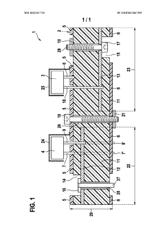
EMC filter having shielding
PatentWO2022017715A1
Innovation
- An EMC filter with a multilayer printed circuit board design featuring a ground layer that shields internal conductive layers, including filter capacitors connected to these layers, effectively reducing radiation and improving damping.
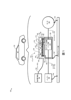
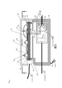
Electromagnetic interference suppression for vehicle
PatentWO2019182132A1
Innovation
- The implementation of a configuration that includes a switching circuit with capacitors and inductors to create a low-impedance path for noise currents, specifically using a second capacitor to connect the gate drive circuit ground to the inverter housing ground, effectively shunting noise currents to the ground plane and reducing radiated emissions in the VHF band.


Regulatory Framework for Automotive EMC Certification
The automotive industry operates under stringent electromagnetic compatibility (EMC) regulations to ensure vehicle safety and functionality. CISPR 25 (Comité International Spécial des Perturbations Radioélectriques) stands as the primary international standard governing EMC requirements for vehicles and on-board electronic components, with specific focus on radio disturbance characteristics protection.
For On-Board Chargers (OBCs) in electric vehicles, CISPR 25 establishes precise emission limits across various frequency bands, typically ranging from 150 kHz to 1 GHz. These limits are categorized into five classes (1-5), with Class 5 being the most stringent. OBCs must typically meet Class 3 or higher requirements, depending on their proximity to sensitive electronic systems.
The regulatory landscape extends beyond CISPR 25 to include complementary standards such as ISO 11452 (immunity to radiated disturbances) and ISO 7637 (electrical transient conduction). Together, these form a comprehensive framework that manufacturers must navigate during product development and certification.
Regional variations add complexity to EMC compliance. While European markets follow ECE R10 regulations (based on CISPR 25), the United States adheres to SAE J551/J1113 standards, and Japan implements its own JASO standards. These regional differences necessitate careful planning for global market access.
Testing methodologies prescribed by these regulations include conducted emission measurements using Line Impedance Stabilization Networks (LISN), radiated emission tests in anechoic chambers, and immunity testing against external electromagnetic interference. For OBCs specifically, testing must occur in various operational modes, including standby, charging, and load transitions.
Certification processes typically involve pre-compliance testing during development, followed by formal verification at accredited laboratories. Documentation requirements include detailed test reports, technical construction files, and declarations of conformity. The certification timeline can significantly impact product launch schedules, often requiring 3-6 months for completion.
Recent regulatory trends show increasingly stringent limits as vehicle electronics density grows. The transition to higher switching frequencies in power electronics has prompted regulatory bodies to extend frequency range requirements, with some regions now requiring testing up to 6 GHz to address potential 5G interference concerns.
Cost-Performance Analysis of EMI Suppression Solutions
The cost-performance analysis of EMI suppression solutions for On-Board Chargers (OBCs) reveals significant trade-offs between implementation expenses and electromagnetic compatibility effectiveness. Common suppression techniques include passive filtering components, shielding, and PCB layout optimization, each with distinct cost implications and performance benefits.
Passive filtering solutions, such as common-mode chokes and X/Y capacitors, represent a moderate cost investment ranging from $5-30 per component depending on current ratings and material quality. These components offer excellent performance-to-cost ratios, typically providing 20-40 dB attenuation in critical frequency bands while constituting only 5-8% of total OBC manufacturing costs.
Shielding solutions demonstrate more variable cost-effectiveness. Metal enclosures and compartmentalization can increase production costs by 10-15% but deliver consistent EMI reduction across broad frequency ranges. Specialized shielding materials like mu-metal offer superior performance at high frequencies but at premium costs, sometimes exceeding $50 per square foot, making them suitable only for targeted applications rather than comprehensive solutions.
PCB layout optimization presents perhaps the most favorable long-term cost-performance ratio. While requiring significant upfront engineering investment ($10,000-30,000 in design time), optimized layouts with proper ground planes, controlled impedance traces, and strategic component placement can reduce EMI by 15-25 dB without recurring component costs. This approach becomes increasingly cost-effective at higher production volumes.
Integrated filter modules combining multiple suppression techniques offer balanced solutions, with costs ranging from $40-120 per unit but delivering comprehensive protection across the CISPR 25 frequency spectrum. These modules simplify assembly and reduce manufacturing variability, though at higher unit costs than discrete component approaches.
The analysis indicates that hybrid approaches typically deliver optimal cost-performance outcomes. Low-volume OBC production benefits from standardized filter modules despite higher unit costs, while high-volume manufacturing justifies custom PCB layout optimization and discrete filtering components. Manufacturers must consider not only direct component costs but also testing expenses, potential redesign iterations, and compliance failure risks when selecting EMI suppression strategies.
Unlock deeper insights with Patsnap Eureka Quick Research — get a full tech report to explore trends and direct your research. Try now!
Generate Your Research Report Instantly with AI Agent
Supercharge your innovation with Patsnap Eureka AI Agent Platform!