Method of fabricating piezoelectric vibrating piece, wafer, apparatus having the piezoelectric vibrating piece

一种压电振动片、晶圆的技术,应用在压电/电致伸缩器件的制造/组装、用于压电器件或电致伸缩器件的材料选择、压电器件/电致伸缩器件等方向,能够解决维护性能退化等问题,达到减少数量、实现维护性能的效果

Active Publication Date: 2009-08-19
SII CRYSTAL TECH
View PDF4 Cites 11 Cited by
  • Summary
  • Abstract
  • Description
  • Claims
  • Application Information

AI Technical Summary

Problems solved by technology

Therefore, although the frequency adjustment operation can be efficiently performed by simultaneously performing frequency measurement on a plurality of piezoelectric plates, contrary to this, degradation in maintenance performance is caused

Method used


Image

  • Method of fabricating piezoelectric vibrating piece, wafer, apparatus having the piezoelectric vibrating piece
  • Method of fabricating piezoelectric vibrating piece, wafer, apparatus having the piezoelectric vibrating piece
  • Method of fabricating piezoelectric vibrating piece, wafer, apparatus having the piezoelectric vibrating piece

Examples


no. 1 example 1

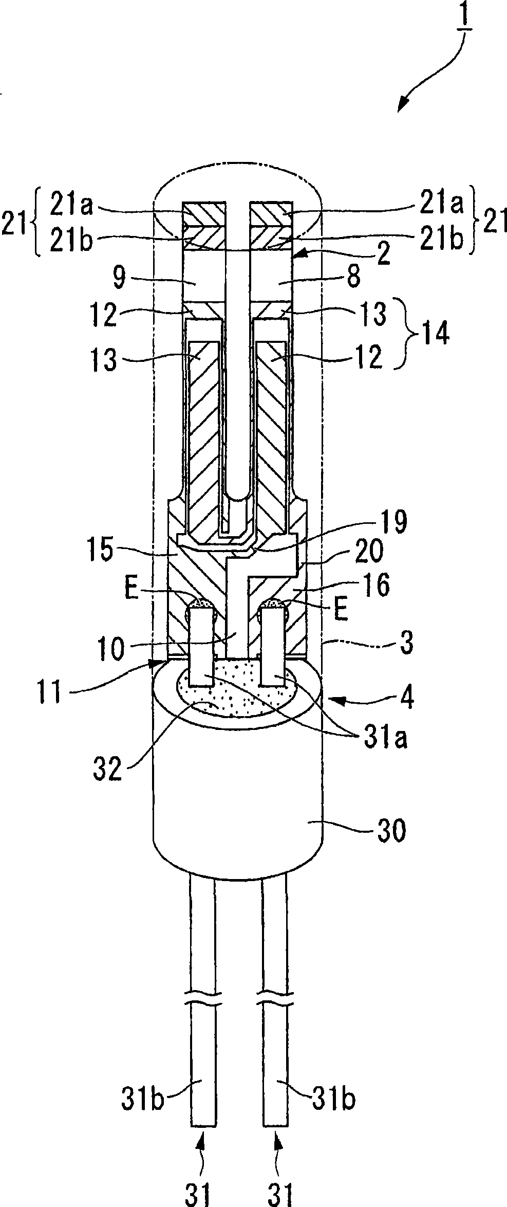
[0076] will refer to the following Figure 1 to Figure 11 The first embodiment according to the present invention is explained. Furthermore, according to this embodiment, as the piezoelectric vibrator 1 , an example of a cylindrical package type piezoelectric vibrator will be explained.

[0077] Such as Figure 1 to Figure 3 As shown, the piezoelectric vibrator 1 of this embodiment includes a piezoelectric vibrating piece 2, a housing 3 housing the piezoelectric vibrating piece 2 inside, and a plug 4 constituting an airtight terminal that hermetically seals the piezoelectric vibrating piece 2. The vibrating piece 2 is enclosed inside the housing 3 .

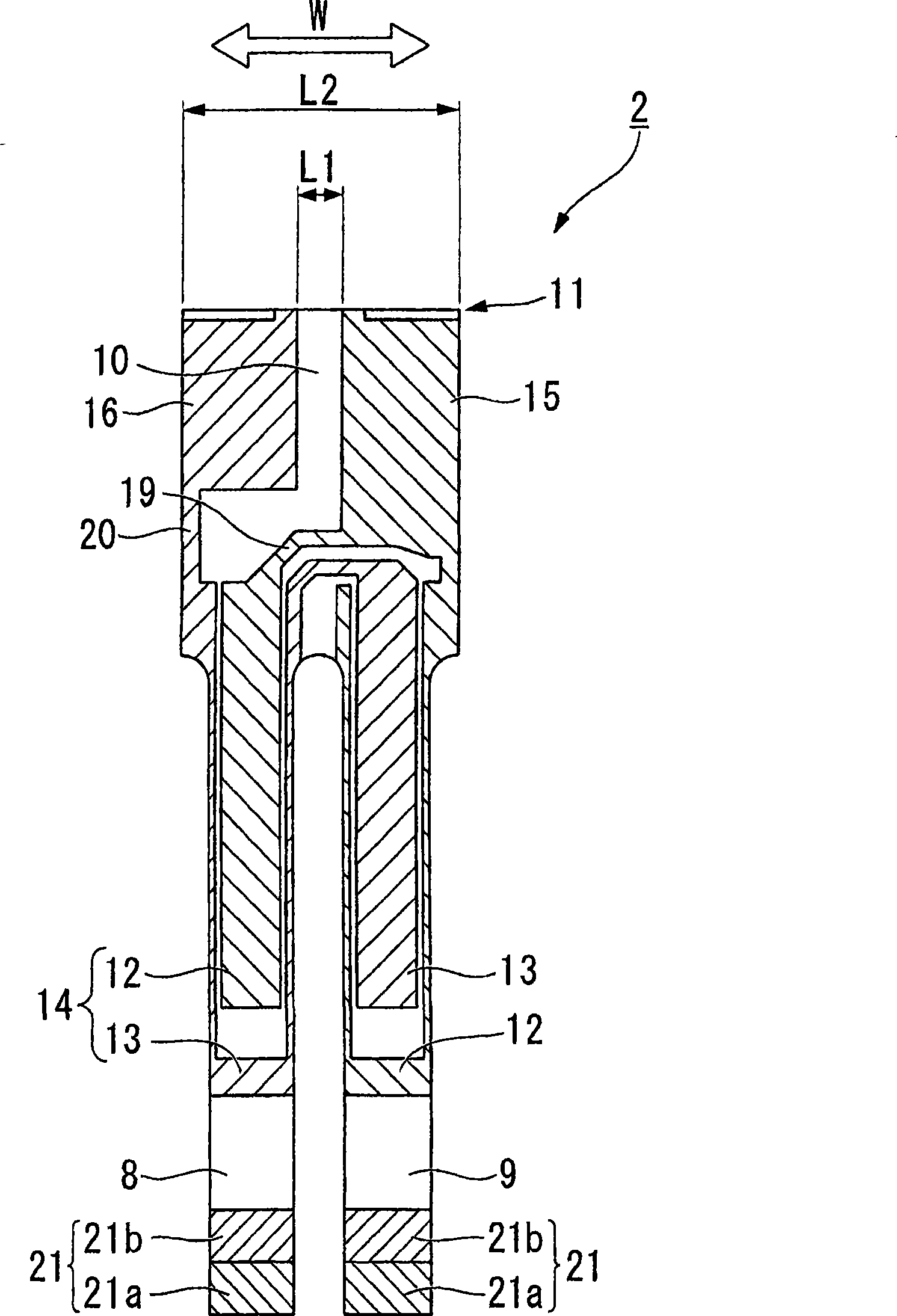
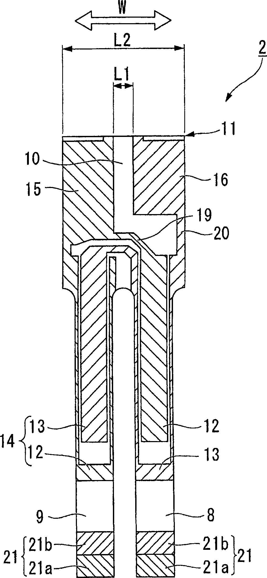
[0078] Such as figure 2 and image 3 As shown, the piezoelectric vibrating piece 2 is a tuning-fork type vibrating member formed of a piezoelectric material such as quartz, lithium tantalate, lithium niobate, etc., and vibrates when a predetermined voltage is applied thereto.

[0079] The piezoelectric vibrating piece 2 inc...

no. 2 example

[0124] Next, refer to Figure 12 A second embodiment according to the present invention is explained. In addition, in the second embodiment, the same parts as the constituent elements of the first embodiment are assigned the same symbols, and their descriptions are omitted.

[0125] The second embodiment differs from the first embodiment in the electrodes formed in the electrode forming step. That is, although according to the first embodiment, the pair of extension electrodes S2, S3 is simply formed, according to the second embodiment, a common extension electrode S4 is formed in addition to the pair of extension electrodes S2, S3.

[0126] Explaining in detail, according to this embodiment, in the electrode forming step, as Figure 12 As shown, a common extension electrode S4 is formed by electrically connecting a plurality of extension electrodes S2 on one side, respectively. That is, the common extension electrode S4 is formed in a state of conduction with all the mount...


PUM


Abstract

To carry out frequency adjustment easily, accurately and efficiently and achieve low cost formation and promotion of maintenance performance without being influenced by a size of a piezoelectric vibrating piece, there is provided a method of fabricating a piezoelectric vibrating piece which is a method of fabricating a piezoelectric vibrating pieces having a piezoelectric plate 11, a pair of exciting electrodes 12, 13, and a pair of mount electrodes electrodes 15, 16 by utilizing a wafer S, the method including an outer shape forming step of forming a frame portion S1 at the wafer and forming a plurality of piezoelectric plates to be connected to the frame portion by way of a connecting portion 11a, an electrode forming step of respectively forming pairs of exciting electrodes and pairs of mount electrodes to the plurality of piezoelectric plates and forming a plurality of pairs of extended electrodes S2, S3 to be respectively electrically connected to the pairs of mount electrodes by way of the connecting portion, a frequency adjusting step of adjusting a frequency of the piezoelectric plate while applying a drive voltage between the pair of the extended electrodes, and a cutting step of fragmenting the plurality of piezoelectric plates.

Description

technical field [0001] The present invention relates to a method of manufacturing a piezoelectric vibrating piece, a piezoelectric vibrating piece manufactured by the manufacturing method, a wafer for producing a piezoelectric vibrating piece, a piezoelectric vibrator having a piezoelectric vibrating piece, an oscillator, and an electronic device And a radio-wave timepiece with a piezoelectric vibrating plate. Background technique [0002] In recent years, a mobile phone or a mobile information terminal device uses a piezoelectric vibrator using quartz or the like as a time source, a timing source of a control signal or the like, a reference signal source, or the like. As such a piezoelectric vibrator, various vibrators are known, for example, a piezoelectric vibrator having a tuning-fork type piezoelectric vibrating piece, a piezoelectric vibrator having a piezoelectric vibrating piece performing thickness-slip vibration, and the like are known. [0003] Explain by taking ...

Claims


Application Information

Patent Timeline
Patent Type & Authority Applications(China)
IPC IPC(8): H03H3/02H03H9/13H01L41/09H01L41/18H01L41/22H01L41/253H01L41/313H01L41/332H01L41/338H03B5/32H03H3/04H03H9/19H03H9/215
CPCH03H3/02H03H9/21H03H9/1021H03H3/04H03H2003/026H03H2003/0442Y10T29/42Y10T29/49147Y10T29/49155Y10T29/49798
Inventor 小林高志
Owner SII CRYSTAL TECH
Why Eureka
Try Eureka