Dual clutch transmission

A dual-clutch and transmission technology, which is applied to vehicle gearboxes, transmissions, transportation and packaging, etc., can solve the problems of increasing structural expenditure and cost expenditure, increasing weight, and the fact that separate transmissions are rarely beneficial, so as to achieve low structural space requirements and Effects of weight and manufacturing costs, short structural ends, efficient utilization of structural space

A dual-clutch and transmission technology, which is applied to vehicle gearboxes, transmissions, transportation and packaging, etc., can solve the problems of increasing structural expenditure and cost expenditure, increasing weight, and the fact that separate transmissions are rarely beneficial, so as to achieve low structural space requirements and Effects of weight and manufacturing costs, short structural ends, efficient utilization of structural space

CN101535682AInactive Publication Date: 2009-09-16ZF FRIEDRICHSHAFEN AG

Image

  • Dual clutch transmission
  • Dual clutch transmission
  • Dual clutch transmission

Examples


Embodiment Construction

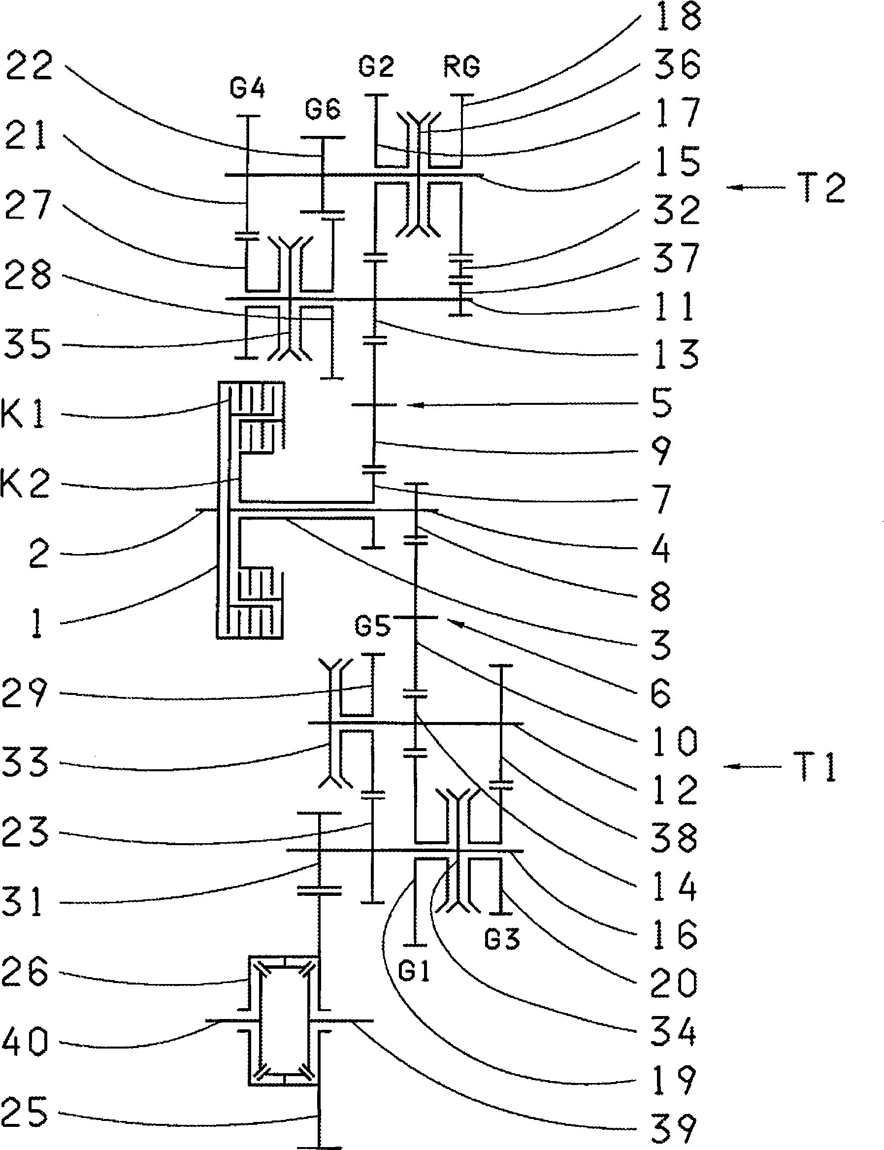
[0035] Accordingly, figure 1 A schematic diagram of a transmission for a six-speed dual-clutch transmission mounted on a front transverse motor vehicle is shown in . In this dual clutch transmission, the dual clutch 1 consisting of two starting clutches K1, K2 drives two coaxial transmission input shafts 3 and 4 according to the sequential control of the two clutches K1 and K2, the dual clutch or directly with The crankshaft 2 of the internal combustion engine (not shown) is connected or, for vibration damping, advantageously via a torsional vibration damper or a dual mass flywheel, to the crankshaft 2 of the internal combustion engine (not shown). Here, the input shaft 4, designed as an inner solid shaft, drives the group of odd gears G1, G3, G5, while the transmission input shaft 3, designed as an outer hollow shaft, drives the group of even gears G2, G4, G6 and the reverse gear RG. The reverse gear RG is advantageously always assigned to the even gear group G2 , G4 , G6 a...


PUM


Abstract

The invention relates to a dual clutch transmission, for example for a motor vehicle, with a dual clutch (1) consisting of two starting clutches (K1, K2) via which a drive motor can be connected respectively to one of two drive input shafts (3, 4) arranged coaxially to one another, each of the two drive input shafts (3, 4) being assigned a group of gears (G1, G2, G3, G4, G5, G6, G7, RG). To achieve as compact a construction as possible, in particular a small axial construction length, in the dual clutch transmission, the groups of gears are constructed as partial transmissions (T1, T1', T1'', T2, T2') mounted to the side of the dual clutch (1), which each have a counter shaft (11, 12) and a main shaft (15, 16) constructed as a transmission output shaft, wherein each partial transmission (T1, T1', T1'', T2, T2') can be driven via exactly one effective partial transmission link (5, 5', 6, 6') between the associated drive input shaft (3, 4) and the counter shaft (11, 12) of the partial transmission (T1, T1', T1'', T2, T2').

Description

technical field [0001] The invention relates to a dual clutch transmission according to the preamble of claim 1 . Background technique [0002] Dual-clutch transmissions are known and proven as gearshift transmissions for motor vehicles with virtually no interruption of tractive force. The gearshift without interruption of traction avoids load changes and speed disturbances, resulting in a more comfortable ride and improved acceleration capability. In the usual construction described in DE 198 21 164 A1, which is structured in a classified manner, the double clutch is provided with two starter clutches, for example designed as wet-running multi-plate clutches, which are each connected to the transmission input shaft. The two transmission input shafts are arranged coaxially with one another, one input shaft being designed as a hollow shaft in which the other input shaft projects as an inner central shaft or solid shaft, protruding from the hollow shaft. Each input shaft is ...

Claims


Application Information

Patent Timeline
16 Sep 2009
Publication
CN101535682A
IPC
F16H3/08
CPC
F16H2003/0931; F16H2200/0052; F16H3/006; F16H2200/0056; F16H3/093; Y10T74/19233
Inventors
格哈德·贡波采伯格