

An Online Dynamic Balance Measurement and Control System for High Precision Machining Spindle
A high-precision processing, measurement and control system technology, applied in the static/dynamic balance test, machine/structural component test, measuring device, etc., can solve the problem of long running time of the system, slow response speed, difficulty in optimizing each function, etc. question
Patent Information
- Authority / Receiving Office
- CN · China
- Patent Type
- Patents(China)
- Current Assignee / Owner
- Publication Date
- 2018-07-17
Smart Images
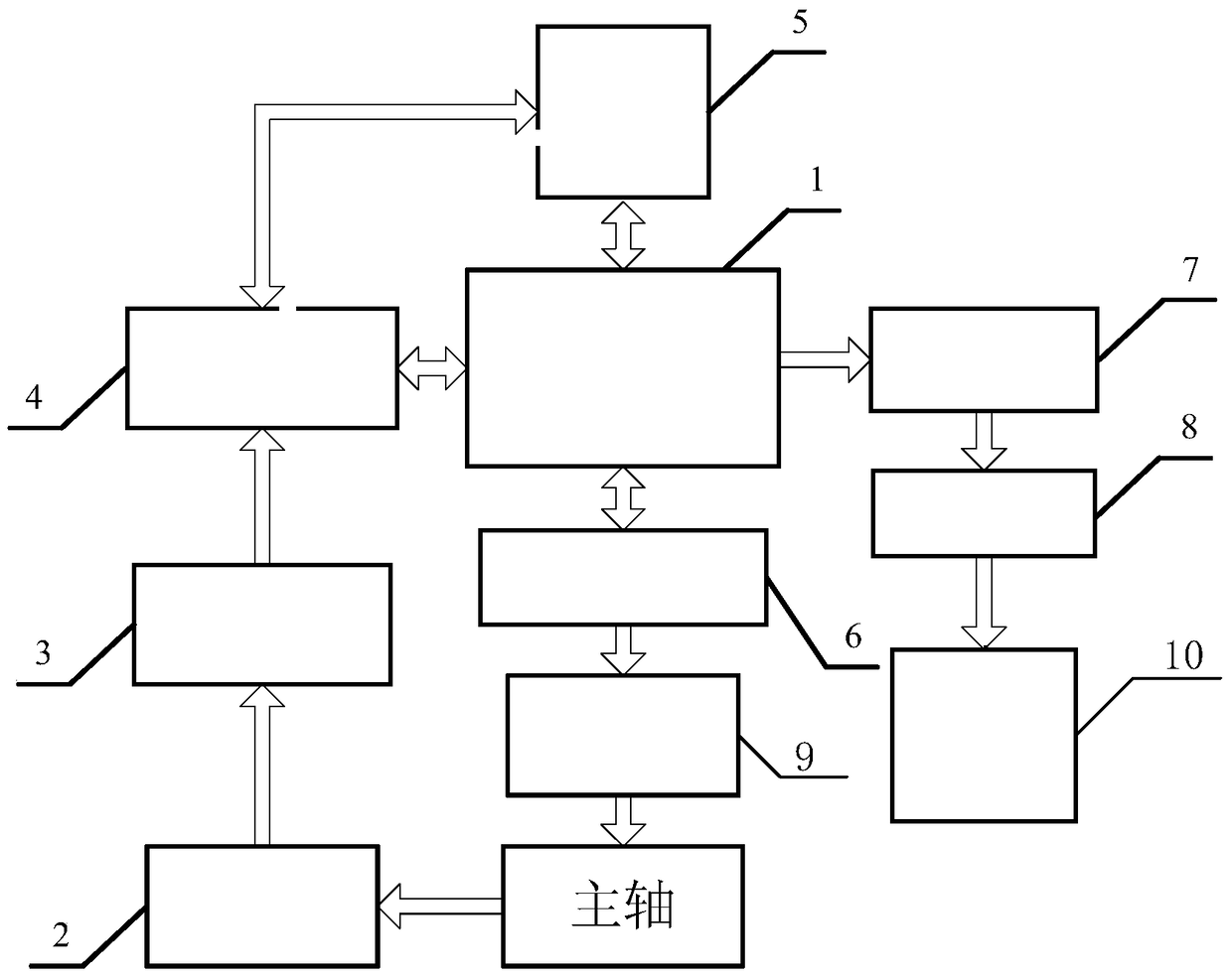
Figure 1 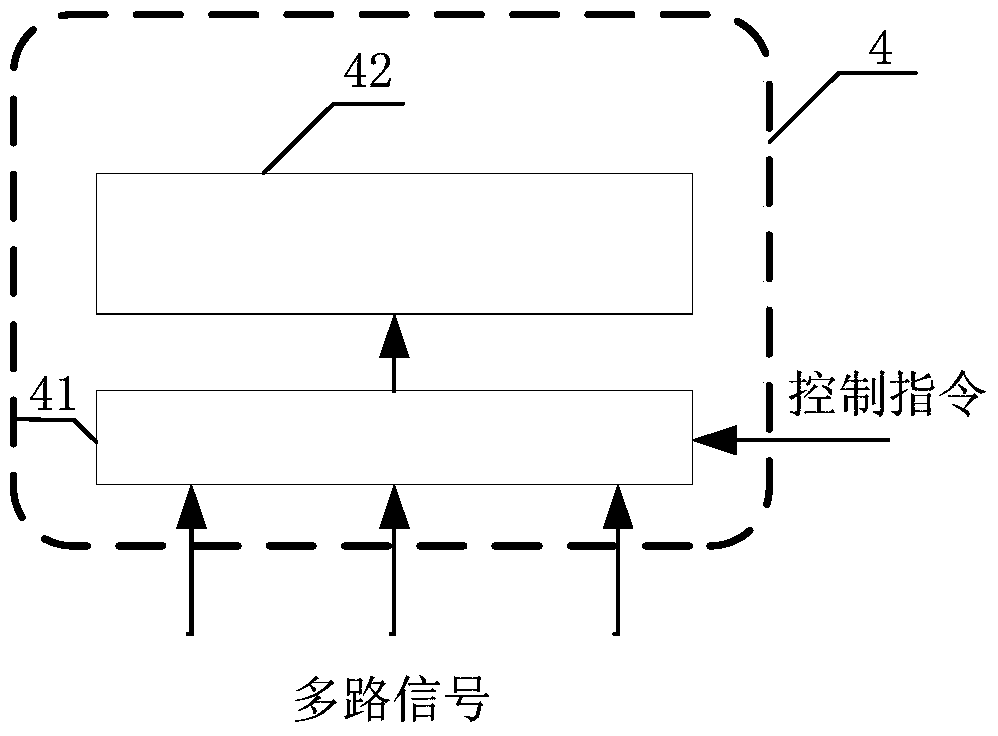
Figure 2 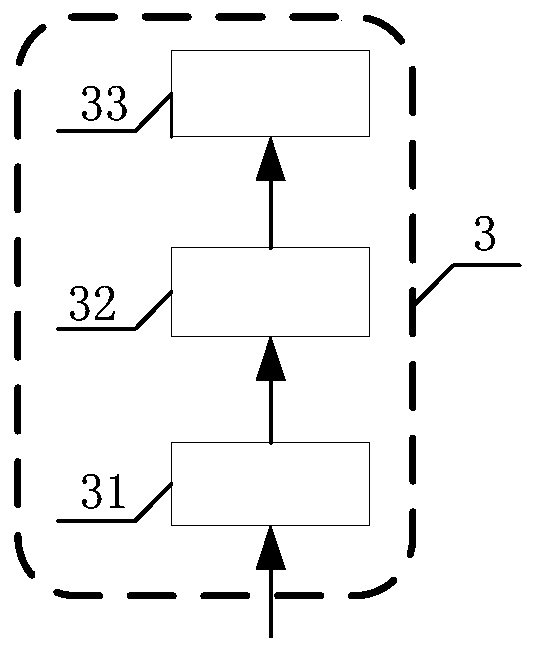
Figure 3
Abstract
Description
Technical field
[0001] The invention belongs to the technical field of spindle high-speed dynamic balance, and relates to an online dynamic balance measurement and control system for high-precision machining spindles. Background technique
[0002] The development direction of modern machining is high-speed, high-precision, and high-efficiency. The high-speed of machine tools has become the current development trend of machine tools. This trend puts forward higher requirements for machine tools, and the spindle is the core component of machine tools to a large extent Determines the processing performance of the machine tool. In the actual processing engineering, due to the influence of factors such as manufacturing error, material unevenness and installation error, the spindle must have an imbalance. Unbalance usually leads to spindle vibration, which is particularly obvious on high-speed machine tools. Excessive spindle vibration will directly affect machining accuracy, and at t...
Examples
Embodiment Construction
[0025] The present invention will be described in further detail below in conjunction with the accompanying drawings:
[0026] reference figure 1 , figure 2 and image 3 , The online dynamic balance measurement and control system of the high-precision machining spindle of the present invention includes a signal conditioning circuit 3, a signal acquisition circuit 4, a DSP processing circuit 5, a human-computer interaction terminal 1, a single-chip microcomputer control circuit 6, and a control circuit for controlling the dynamic balance of the spindle The dynamic balance control terminal 9, the signal detection circuit 2 used to detect the spindle displacement signal, the acceleration signal and the temperature signal of the user's desired position; the output end of the signal detection circuit 2 is connected to the input end of the signal conditioning circuit 3, and the signal The output terminal of the conditioning circuit 3 is connected with the input terminal of the signal ...