
Fault diagnosis method for sequentially switched parallel regulator
A shunt regulator and sequence switch technology, which is applied in the monitoring of current collectors, photovoltaic systems, photovoltaic modules, etc., can solve the problems of inability to accurately detect and locate faults of shunt regulators, and achieve accurate fault positioning and fault missed detection rate. Low, low detection volume effect
Patent Information
- Authority / Receiving Office
- CN · China
- Patent Type
- Applications(China)
- Current Assignee / Owner
- Publication Date
- 2019-05-31
Smart Images
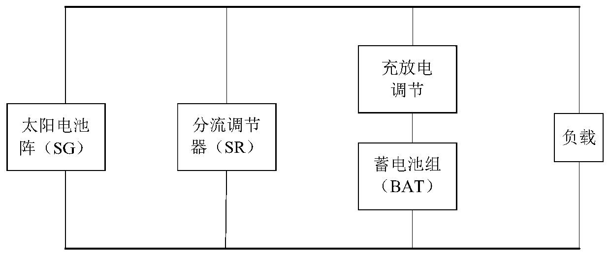
Figure 1 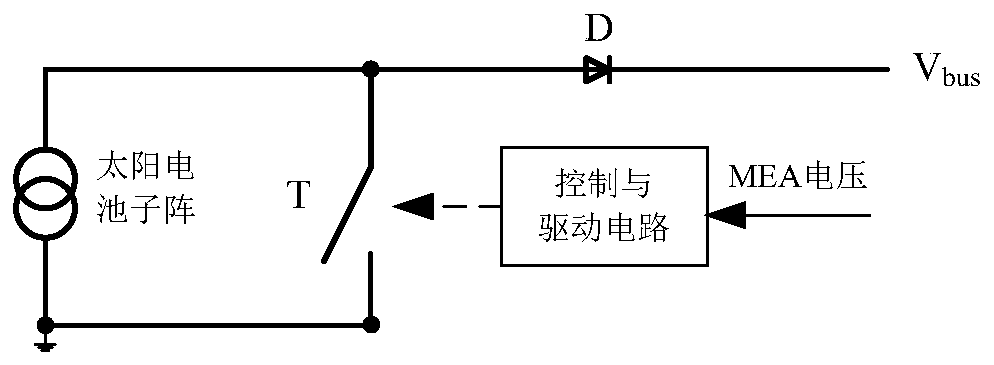
Figure 2 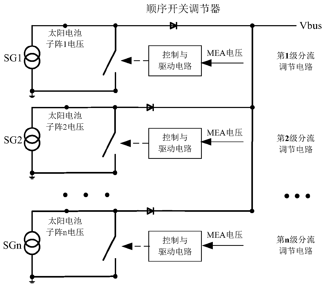
Figure 3
Abstract
Description
technical field
[0001] The invention relates to the field of fault diagnosis of spacecraft power supply controllers, in particular to a fault diagnosis method for sequential switching shunt regulators. Background technique
[0002] Shunt regulators are widely used in spacecraft power controllers to regulate the output power of solar arrays and bus voltage. From the perspective of energy transmission, the topology of the spacecraft power system can be divided into direct energy transfer (DET) and peak power tracking. Shunt regulators are commonly used in applications such as figure 1 The DET topology shown.
[0003] The block diagram of the prior art sequence switch shunt adjustment principle is as follows: figure 2 As shown, the shunt regulator divides the solar array into n identical sub-arrays, the positive end of each sub-array is grounded through the switch tube T, and connected to the bus V through the diode D bus . According to the different states of the switchi...
Examples
Embodiment Construction
[0041] The present invention will be described in further detail below with reference to the figures and examples, so that those skilled in the art can better understand the present invention and implement it, but the examples given are not intended as limitations of the present invention.
[0042] The following is a detailed description of the sequential switch shunt regulator fault diagnosis method. The structure of the sequential switch shunt regulator in this embodiment is as follows image 3 shown.
[0043] Assume that a satellite power supply adopts a sequential switch shunt regulator to adjust the output power of the solar cell array and the bus voltage. There are 12 levels of shunt regulation circuits in total, of which the first level shunt regulation circuit has the priority of shunting, followed by the second level, the third level, ... , the 12th stage, adopts the fully regulated busbar topology, and its busbar voltage is constant V bus =100V.
[0044] Adopt the ...