
Electrostatic motor with clearance maintaining structure

a technology of electrostatic motor and clearance maintaining structure, which is applied in the direction of electrostatic motor, electrostatic generator/motor, electrical apparatus, etc., can solve the problems of uneven clearance between stationary and movable members, unbalanced distribution of fine grains between opposing surfaces, etc., and achieves the effect of keeping clearance and easy control

Inactive Publication Date: 2008-05-13
FANUC LTD
View PDF14 Cites 6 Cited by
  • Summary
  • Abstract
  • Description
  • Claims
  • Application Information

AI Technical Summary

Benefits of technology

The present invention provides an electrostatic motor with a stationary member and a movable member that can easily control and keep a clearance between them without using fine grains. This is achieved by providing a protuberance on at least one of the surfaces of the stationary member and the movable member to ensure a proper relative position between them. The protuberance can be integrally formed on the cover film of the stationary member and the movable member or separately provided on each surface. The use of low-friction materials exhibiting an excellent sliding property can further improve the performance of the electrostatic motor.

Problems solved by technology

Therefore, when the movable member moves relative to the stationary member during an operation of the electrostatic motor, the fine grains (or glass beads) tend to move accompanying thereto, which may cause the unbalanced distribution of the fine grains between the opposing surfaces.
If the fine grains (or glass beads) are distributed in an unbalanced manner between the stationary member and the movable member, the clearance between the stationary and movable members may lose uniformity, and thereby the characteristics of the electrostatic motor may be varied.

Method used


Image

  • Electrostatic motor with clearance maintaining structure
  • Electrostatic motor with clearance maintaining structure
  • Electrostatic motor with clearance maintaining structure

Examples


first embodiment

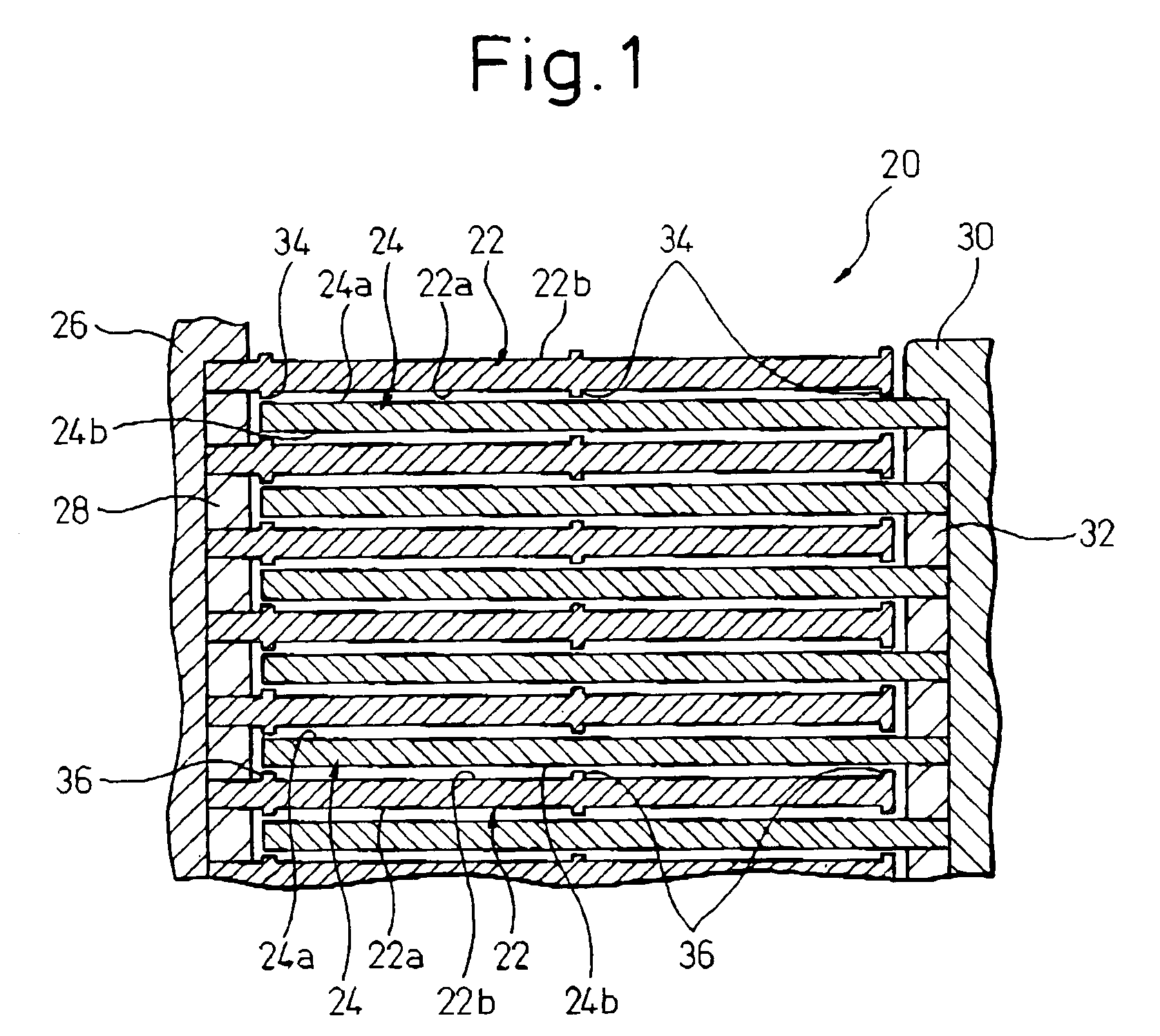
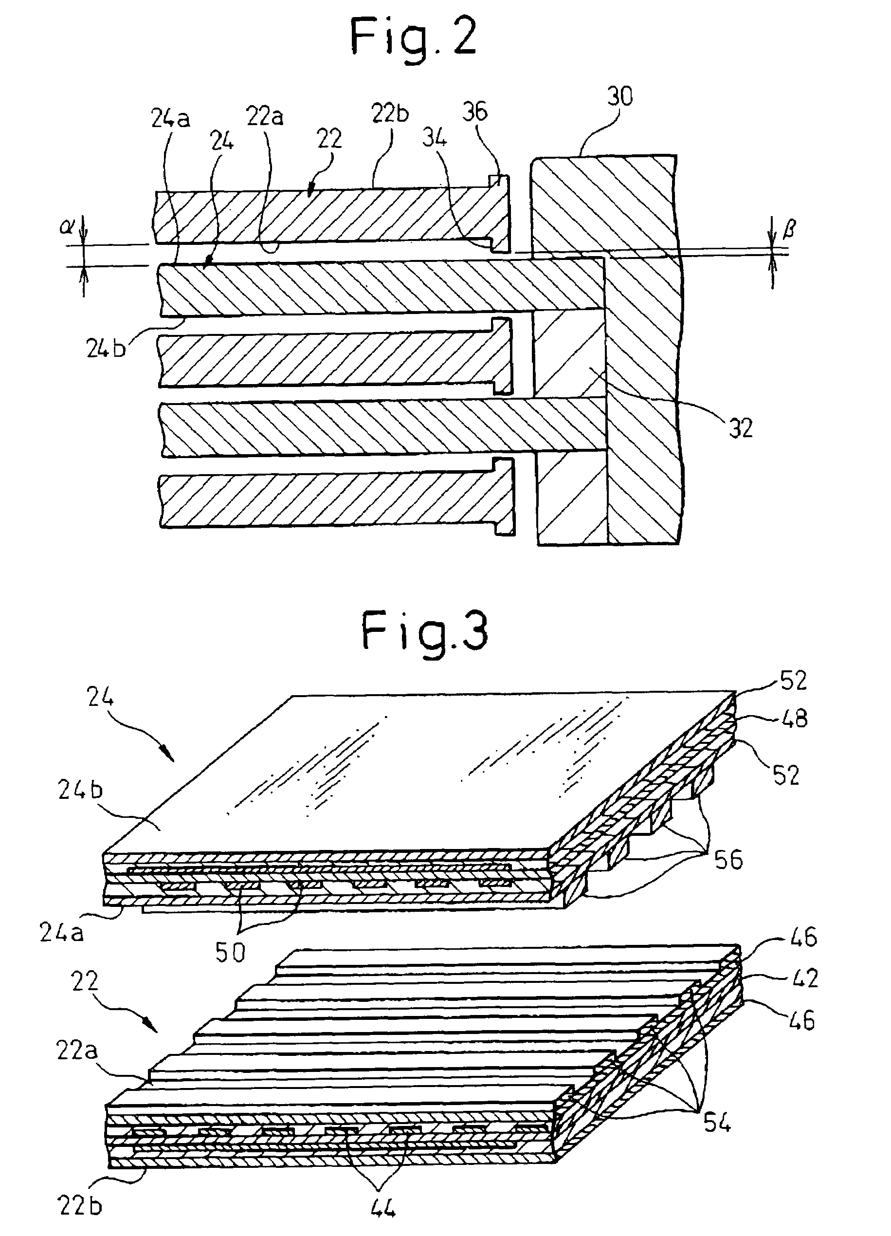
[0042]Next, with reference to FIGS. 1 and 2, the configuration of an electrostatic motor 20 according to the invention is described, that can be applied to the electrostatic motor having the above-described essential configuration.

[0043]Referring to FIG. 1, the electrostatic motor 20 is provided with a film-shaped stationary member 22 including a first major surface 22a and a first back surface 22b opposite to the first major surface 22a, and a film-shaped movable member 24 including a second major surface 24a and a second back surface 24b opposite to the second major surface 24b. The movable member 24 is arranged to be movable relative to the stationary member 22 in a condition where the second major surface 24a is opposed to the first major surface 22a of the stationary member 22. The stationary member 22 and the movable member 24 have film-laminated structures identical respectively to those of the stationary member 1 and the movable member 2 shown in FIGS. 8 to 11. Further, the ...

second embodiment

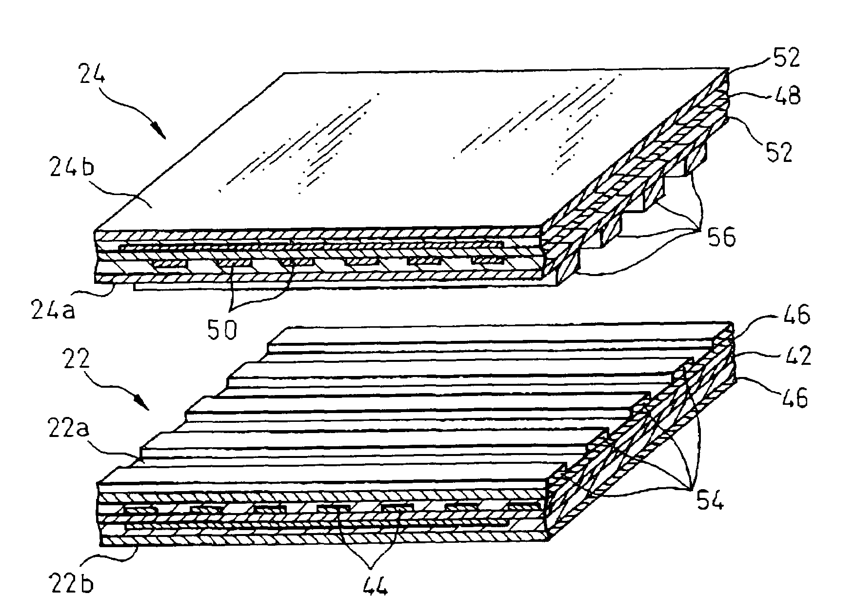
[0050]FIGS. 3 to 7 show an electrostatic motor 40 according to the present invention. The electrostatic motor 40 has a configuration substantially identical to that of the above-described electrostatic motor 20 except for the constitution of a protuberance for maintaining a predetermined clearance between a stationary member and a movable member. Therefore, corresponding components are denoted by common reference numerals, and the description thereof is not repeated.

[0051]The stationary member 22 of the electrostatic motor 40 includes a base film (or an insulating substrate) 42, conductive portions including a plurality of electrodes 44 and current paths (corresponding to electrodes 3a to 3c and current paths 3a′ to 3c′ of the stationary member 1 in FIG. 10) suitably patterned on the opposite surfaces of the base film 42, and cover films 46 attached to the opposite surfaces of the base film 42 and covering the conductive portions. Also, the movable member 24 includes a base film (or...


PUM


Abstract

An electrostatic motor provided with a stationary member including a first major surface and a first back surface opposite to the first major surface; and a movable member including a second major surface and a second back surface opposite to the second major surface, the movable member being arranged to be movable relative to the stationary member in a condition where the second major surface is opposed to the first major surface of the stationary member. The electrostatic motor includes a protuberance provided to project from at least one of the first major surface of the stationary member and the second major surface of the movable member, for ensuring a predetermined clearance between the first major surface and the second major surface. The electrostatic motor may include a plurality of stationary members and a plurality of movable members, assembled with each other in a manner as to alternately arrange the stationary members and the movable members. In this arrangement, the electrostatic motor may further include a back-side protuberance provided to project from at least one of the first back surface of each of the stationary members and the second back surface of each of the movable members, for ensuring a predetermined clearance between the first back surface and the second back surface.

Description

BACKGROUND OF THE INVENTION[0001]1. Field of the Invention[0002]The present invention relates to an electrostatic motor which generates a driving force from an electrostatic force.[0003]2. Description of the Related Art[0004]There has been developed an electrostatic motor in which each of a stationary member (or a stator) and a movable member is constituted by arranging a plurality of electrodes on a film-like insulating substrate, and a multi-phase AC voltage is applied to the respective sets of electrodes of the stationary member and the movable member so as to move the movable member relative to the stationary member. As compared to an electric motor using an electromagnetic force, this type of the electrostatic motor does not require a large mass component, such as a magnetic coil or a permanent magnet, and thus can be easily fabricated in a small size, which permits it to be utilized as, e.g., a drive source for a micro-machine.[0005]Japanese Unexamined Patent Publication (Koka...

Claims


Application Information

Patent Timeline
Patent Type & Authority Patents(United States)
IPC IPC(8): H02N1/00
CPCH02N1/004
Inventor ODAKA, SHUNICHIKARIYA, ISAO
Owner FANUC LTD
Learn More