
Axial turbine wheel with curved leading edge
a technology of axial turbines and leading edges, which is applied in the direction of gas turbine plants, engine manufacture, combustion engines, etc., can solve the problems of loss of efficiency and performance, inability to efficiently manufacture small blade sizes usable with many modern internal combustion engines, and lack of ability to perform well at higher expansion ratios, so as to improve the overall efficiency of the turbocharger, reduce the number of thrust bearing loads, and reduce manufacturing tolerances. effect of small blade sizes
Patent Information
- Authority / Receiving Office
- US · United States
- Patent Type
- Patents(United States)
- Current Assignee / Owner
- Publication Date
- 2015-12-01
Smart Images
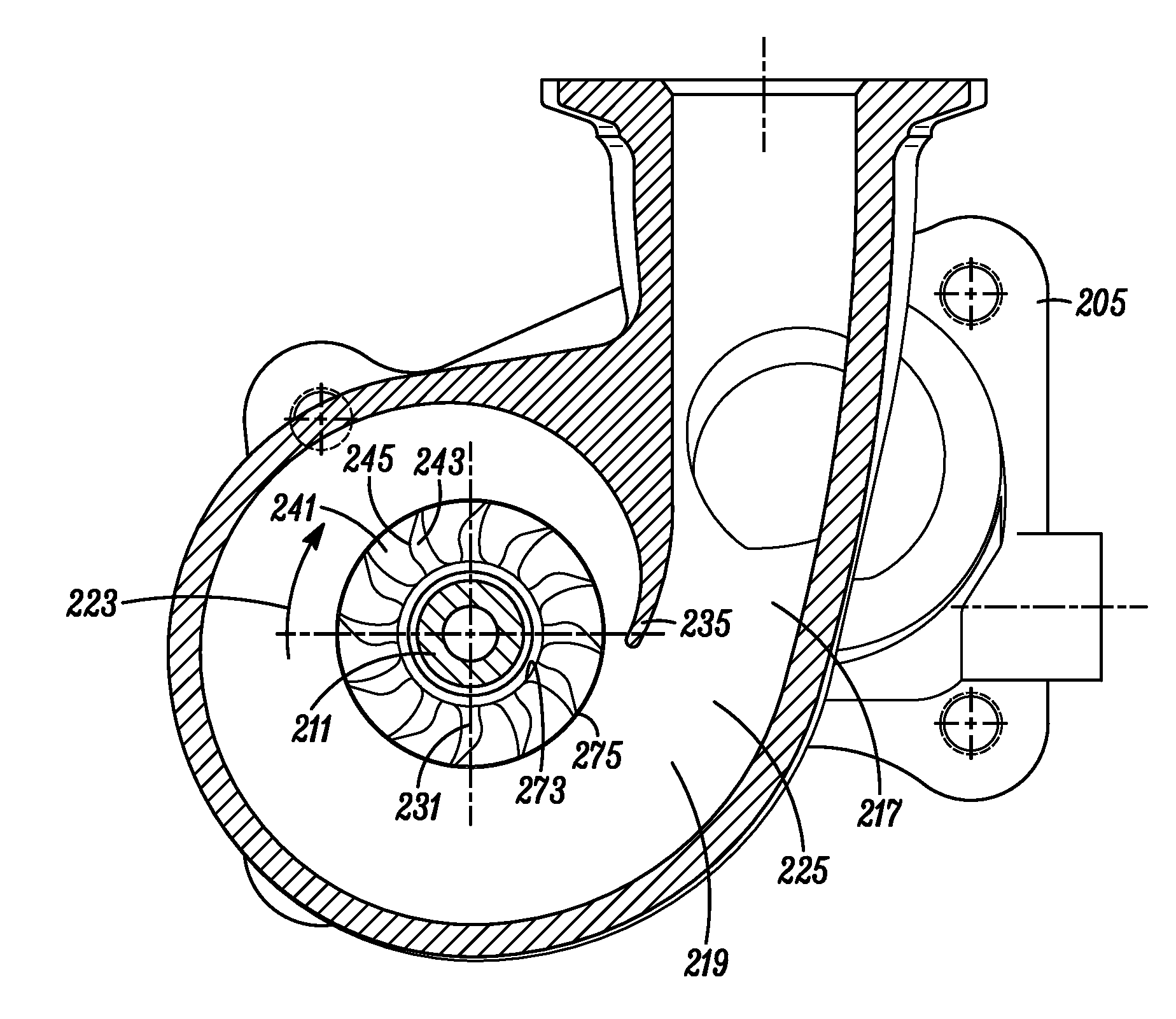
Figure 1 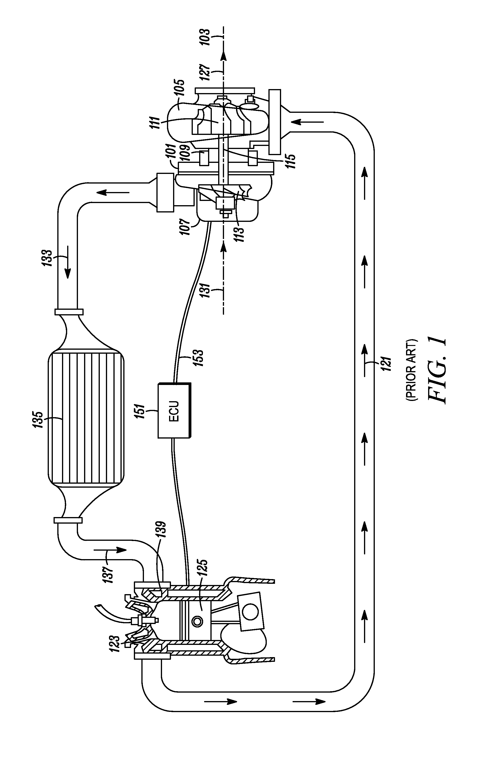
Figure 2 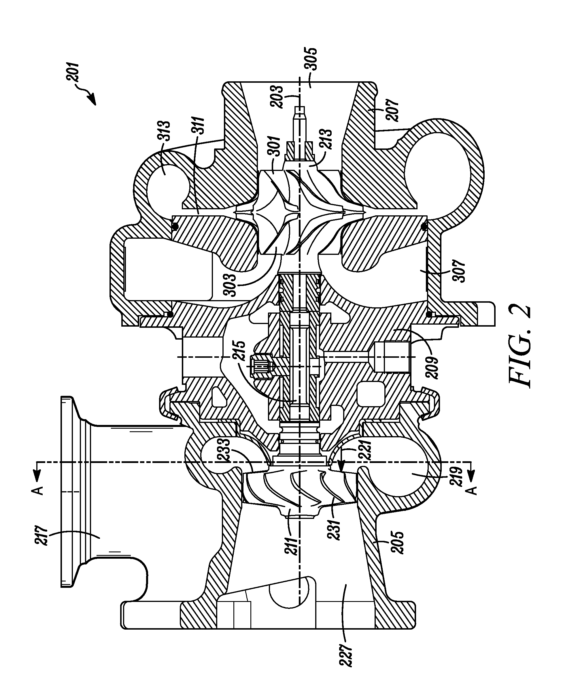
Figure 3
Abstract
Description
[0001] The present invention relates generally to turbochargers and, more particularly, to an axial turbine having a low hub to tip ratio and a curved leading edge.BACKGROUND OF THE INVENTION
[0002] With reference to FIG. 1, a typical turbocharger 101 having a radial turbine includes a turbocharger housing and a rotor configured to rotate within the turbocharger housing along an axis of rotor rotation 103 on thrust bearings and two sets of journal bearings (one for each respective rotor wheel), or alternatively, other similarly supportive bearings. The turbocharger housing includes a turbine housing 105, a compressor housing 107, and a bearing housing 109 (i.e., a center housing that contains the bearings) that connects the turbine housing to the compressor housing. The rotor includes a turbine wheel 111 located substantially within the turbine housing, a compressor wheel 113 located substantially within the compressor housing, and a shaft 115 extending along the axis of rotor rotation...
Examples
Embodiment Construction
[0027]The invention summarized above and defined by the enumerated claims may be better understood by referring to the following detailed description, which should be read with the accompanying drawings. This detailed description of particular preferred embodiments of the invention, set out below to enable one to build and use particular implementations of the invention, is not intended to limit the enumerated claims, but rather, it is intended to provide particular examples of them.
[0028]Typical embodiments of the present invention reside in a motor vehicle equipped with a gasoline powered internal combustion engine (“ICE”) and a turbocharger. The turbocharger is equipped with a unique combination of features that may, in various embodiments, provide the aerodynamic benefits of a zero reaction turbine with the geometric benefits of a fifty percent reaction turbine, and / or provide significantly improved system efficiencies by combining less efficient components in a manner that redu...