
Imaging method and device
An image and control device technology, applied in the direction of electric recording process applying charge pattern, equipment and instrument of electric recording process applying charge pattern, etc. Effects of image shift, improved transportability, good transferability
Patent Information
- Authority / Receiving Office
- CN · China
- Patent Type
- Patents(China)
- Current Assignee / Owner
- Publication Date
- 2008-07-16
- Estimated Expiration
- Not applicable · inactive patent
Smart Images
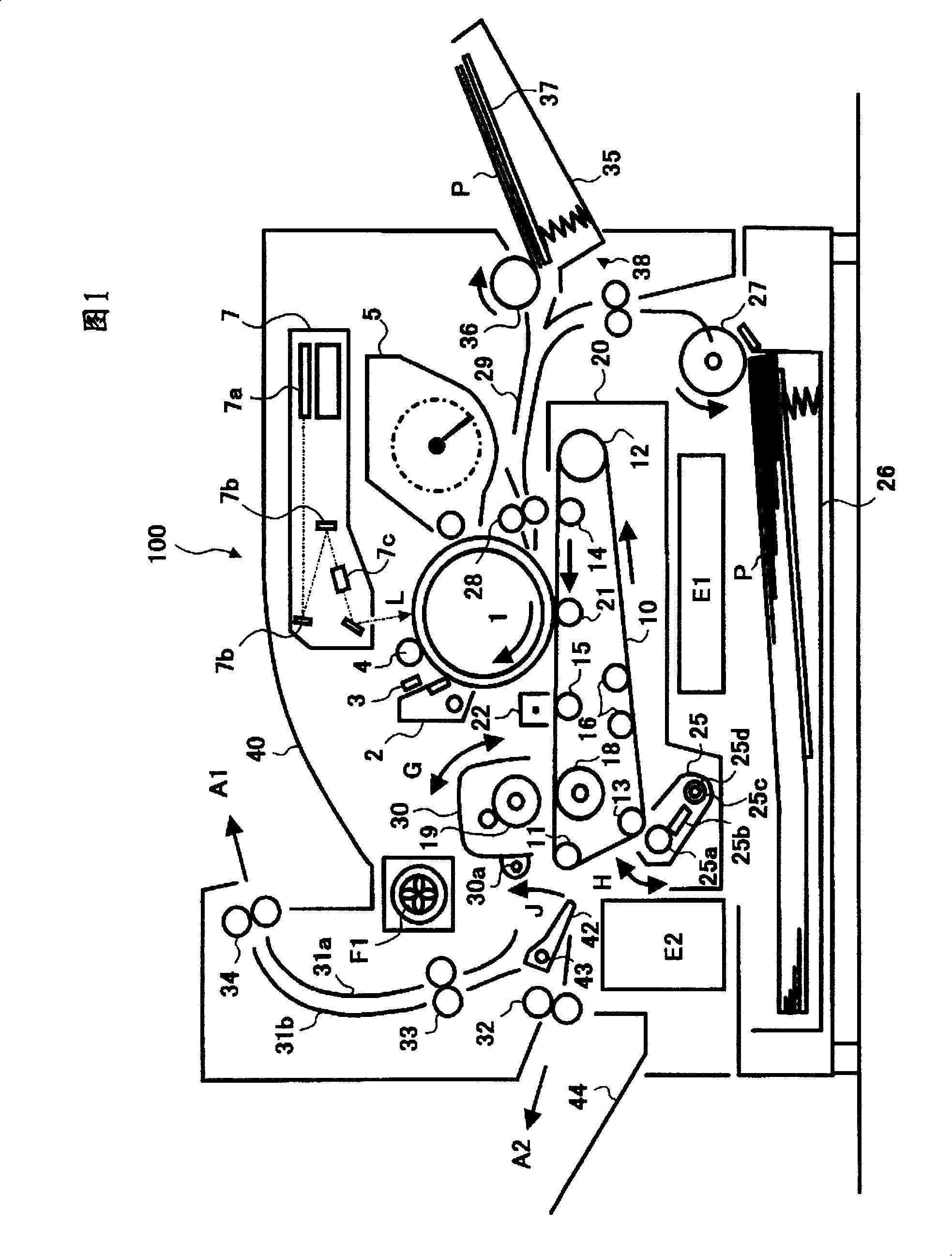
Figure 1 
Figure 2 
Figure 3
Abstract
Description
Technical field
[0001] The invention relates to a method and a device for forming images on both sides of a recording medium. Background technique
[0002] Among image forming devices such as copiers, printers, and facsimile machines, some devices can form images on both sides of a recording medium (for simplicity, hereinafter abbreviated as "paper"). In the conventional double-sided recording image forming apparatus, the following method is generally used: the one-side image (developed image) formed on the image carrier is transferred to the paper, fixed, and then the paper is reversed through a reversing channel, etc. , Feed the paper again, transfer the image of the other side (display image) on the back of the paper, and fix it.
[0003] In the case of double-sided recording in the above manner, there are many problems in ensuring the reliability of paper transportation due to the switching of the paper conveying direction and the paper curling caused by single-sided image fi...
Examples
Embodiment Construction
[0125] The embodiments of the present invention will be described in detail below with reference to the drawings.
[0126] FIG. 1 is a schematic cross-sectional configuration diagram of a printer as an example of an image forming apparatus to which the present invention is applied.
[0127] In the printer 100 shown in the figure, a photoreceptor drum 1 as a first image carrier is disposed substantially in the center of the device. A cleaning device 2, a discharging device 3, a charging device 4, and a developing device 5 are arranged around the photoreceptor drum 1. In the figure, an exposure device 7 is provided above the photoreceptor drum 1, and the laser light L emitted from the exposure device 7 irradiates the photoreceptor 1 at a writing position between the charging device 4 and the developing device 5.
[0128] In this embodiment, the photoreceptor drum 1, the cleaning device 2, the dissipating device 3, the charging device 4, the developing device 5, etc., are assembled i...