
Plate type cold trap for freeze-dryer
A freeze dryer and cold trap technology, which is applied in the field of plate cold traps for freeze dryers, can solve the problem that the power per unit surface area is not suitable for large freeze dryers, the heat exchange area is not fully utilized, and the tubular cold trap traps Water efficiency is low and other problems, to achieve the effect of shortening pre-evacuation time, shortening defrosting time, and reducing equipment investment
Patent Information
- Authority / Receiving Office
- CN · China
- Patent Type
- Patents(China)
- Current Assignee / Owner
- Publication Date
- 2009-09-30
Smart Images
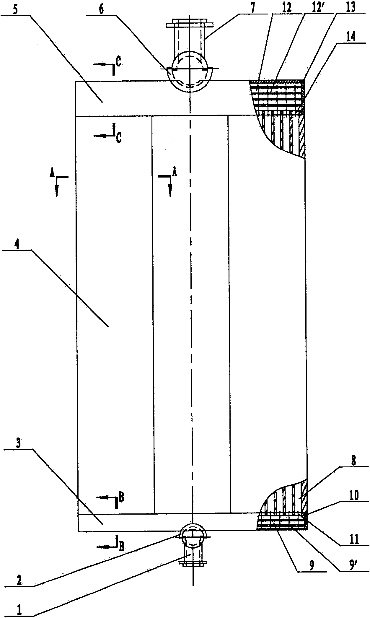
Figure 1 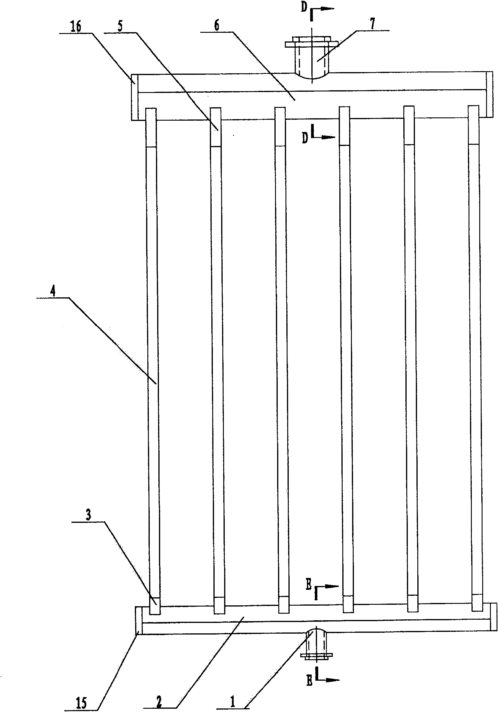
Figure 2 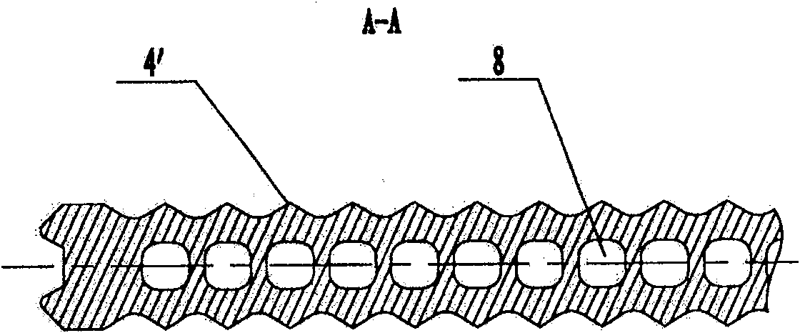
Figure 3
Abstract
Description
technical field
[0001] The invention relates to a vacuum freeze dryer (hereinafter referred to as a freeze dryer), in particular to a plate cold trap for a freeze dryer. Background technique
[0002] Freeze-drying technology is to freeze the water-containing material to the temperature below the eutectic point, so that the water in it becomes ice, and then sublimates the ice into water vapor to escape from the material at an appropriate temperature and vacuum, and uses a cold trap to freeze the Water vapor desublimation, so as to obtain the technology of drying products. When the freeze dryer is working, the vacuum in the freeze-drying chamber is obtained by the vacuum system, which is mainly composed of a vacuum unit and a cold trap. During the drying process, a large amount of sublimated water vapor cannot be completely discharged out of the warehouse by the vacuum unit alone. The vacuum machine is only used to extract non-condensable gas. For the water vapor in the gas, ...
Examples
Embodiment Construction
[0028] Such as figure 1 , 2 , is a schematic diagram of a plate-type cold trap for a freeze dryer, showing a liquid supply main pipe 1, a liquid supply cross header 2, a liquid supply small header 3, a cold trap main board 4, a return small header 5, a return flow Horizontal header box 6 and reflux main pipe 7; several cold trap main boards 4 are arranged in parallel and equidistant or fan-shaped. This scheme is arranged in parallel and equidistant. The lower ends of the small liquid supply headers 3 are installed on the liquid supply cross header 2, and the liquid supply main pipe 1 is installed on the lower side of the liquid supply cross header 2; the upper end of each cold trap main board 4 is equipped with a return flow box 5; the upper end of each small return header 5 is installed on the return cross header 6, and the return main pipe 7 is installed on the upper side of the return cross header 6; each piece has a flow channel inside, and each piece The flow passages a...