
Space three-translational parallel connection mechanism with far-rack single-lever
A three-translation, single-rod technology, applied in the field of robotics, can solve the problems of difficulty in control accuracy, difficult to guarantee the posture of the end effector of the mechanism, etc., and achieve the effect of simplifying the active branch, easily identifying the source of geometric error, and increasing the driven branch.
Patent Information
- Authority / Receiving Office
- CN · China
- Patent Type
- Patents(China)
- Current Assignee / Owner
- Publication Date
- 2010-01-20
- Estimated Expiration
- Not applicable · inactive patent
Smart Images
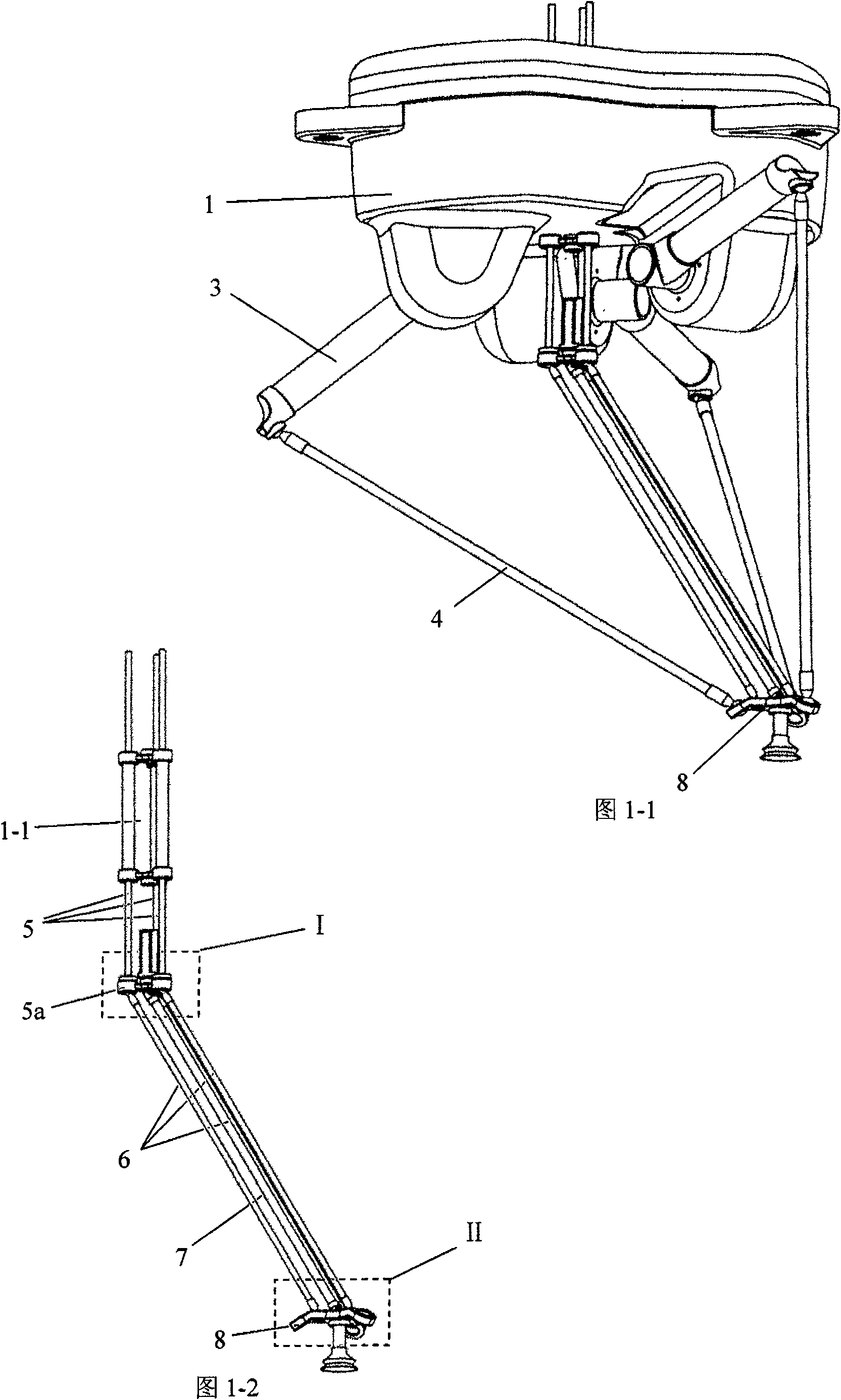
Figure 1 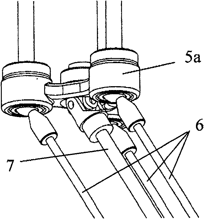
Figure 2 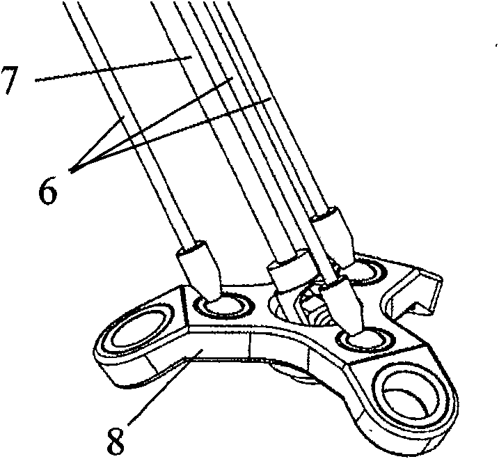
Figure 3
Abstract
Description
technical field
[0001] The invention relates to a robot, in particular to a space three-translation parallel mechanism with a remote frame single rod. Background technique
[0002] U.S. Patent No. 4,976,572 (or WO7703527, EP0250470, CH672079, EP0250470, JP63501760T) discloses a spatially symmetrical three-translation parallel mechanism, which includes three active branch chains, and each branch chain includes two parts, a near frame bar and a far frame bar. There are two types of remote frame rods of this type of mechanism, one is a single rod form, and the two ends of the rod are respectively connected with the near frame rod and the moving platform through a Hooke hinge; the other is a parallelogram formed by two rods, each The two ends of the rod are respectively connected with the near frame rod and the moving platform through ball joints, wherein one end of the near frame rod has only one degree of freedom of movement or rotation relative to the fixed frame, and the oth...
Examples
Embodiment Construction
[0026] The present invention will be further described below in conjunction with accompanying drawing:
[0027] Such as Picture 1-1 , diagram 2-1 , Figure 3-1 As shown, a space three-translational parallel mechanism with a single rod on a far frame consists of a fixed frame 1, a moving platform 8, three active branch chains with the same structure and connections between the fixed frame 1 and the moving platform 8. The fixed frame 1 and a driven branch chain of the moving platform 8 are formed, and the driven branch chain between the fixed frame and the moving platform can limit three rotational degrees of freedom of the moving platform 8 .
[0028] See Figure 4 , the three active branch chains are respectively composed of the driving device 2, the near frame bar 3 and the far frame bar 4; the connection mode between one of the three active branch chains and the fixed frame 1 and the moving platform 8 is as follows: Figure 4 As shown, the drive device 2 is fixedly conn...