
Three-dimensional high definition electric resistivity exploration and direct imaging method
An imaging method and resistivity technology, applied in the field of geological exploration, can solve the problems of inaccurate positioning and shape, complicated calculation of fitting method, and difficult to converge, and achieve the effect of strong anti-interference ability, improved signal-to-noise ratio, and easy rolling measurement.
Patent Information
- Authority / Receiving Office
- CN · China
- Patent Type
- Applications(China)
- Current Assignee / Owner
- Publication Date
- 2008-12-31
- Estimated Expiration
- Not applicable · inactive patent
Smart Images
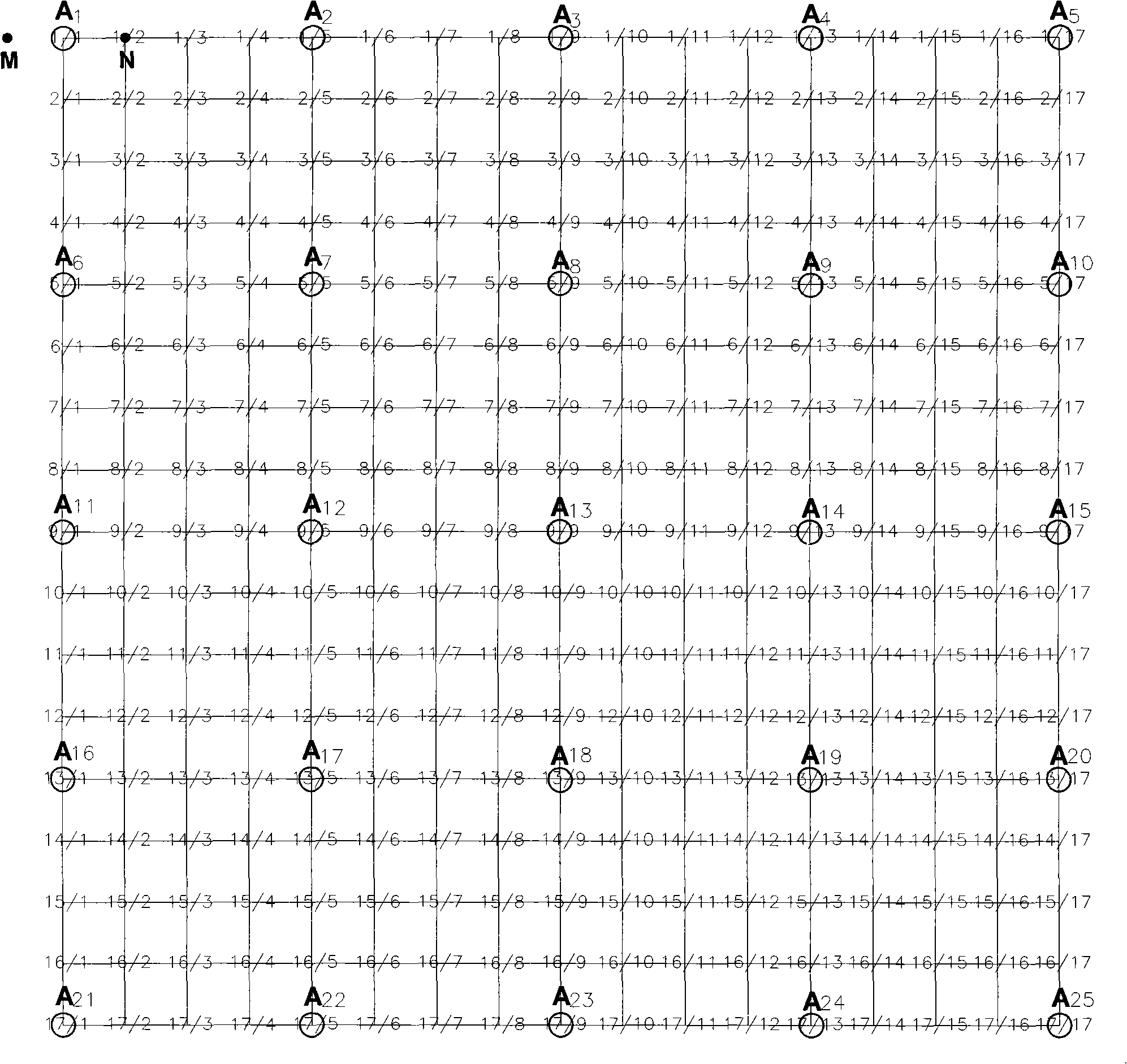
Figure 1 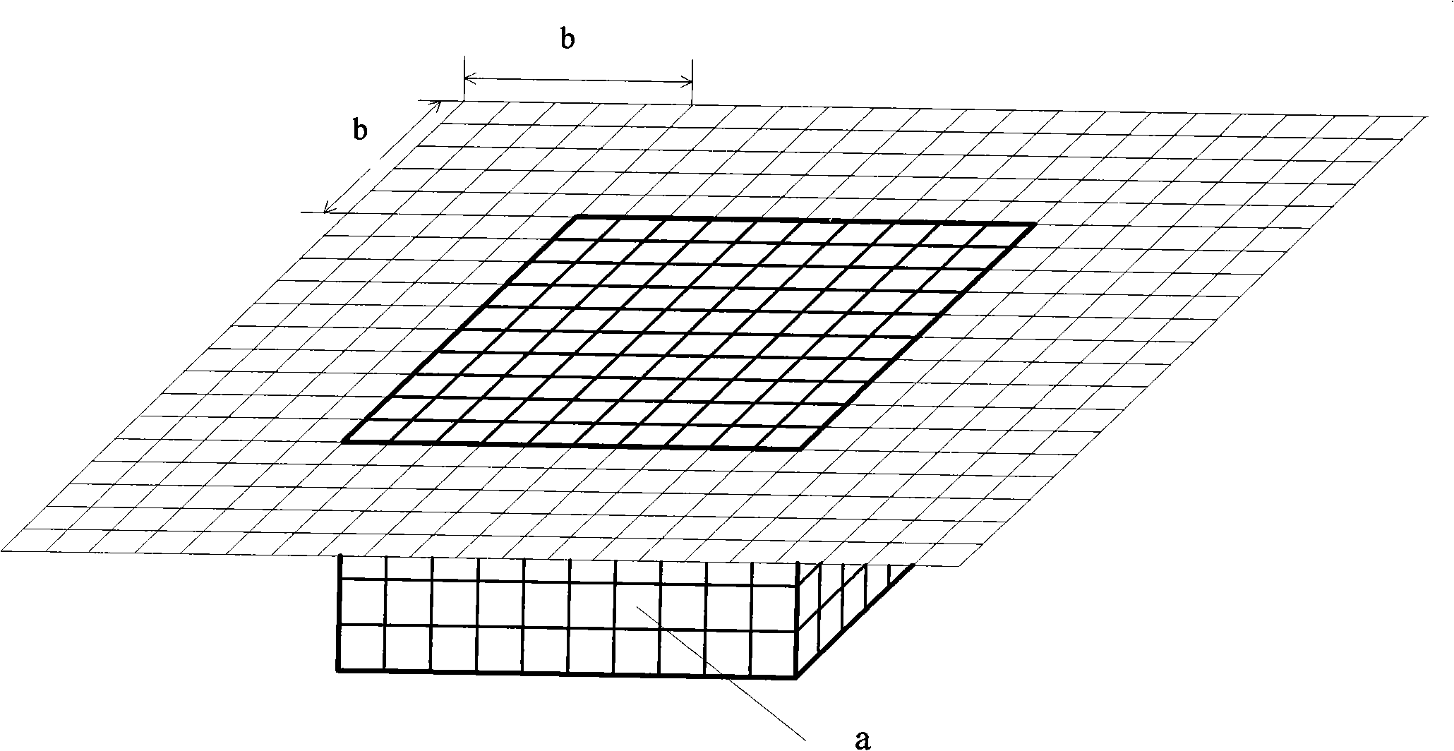
Figure 2 
Figure 3
Abstract
Description
technical field
[0001] The invention belongs to the field of geological exploration, in particular to a three-dimensional high-resolution resistivity exploration and direct imaging method. Background technique
[0002] In order to meet the demand for the detection of shallow fine geological structures, the high-density resistivity method was developed (Griffiths D H, Barker R D. Two-dimensional resistivity imaging and modeling in areas of complex geology. Journal of Applied Geophysics, 1993, 29: 211 ~226). The method adopts smaller electrode pitch and higher density electrode arrangement along the survey line, such as Wenner device, Schlumberger device, dipole-dipole, monopole-monopole, joint profile, intermediate gradient and other devices. Array observation, followed by inversion and fitting imaging. In the detection method with small pole distance and high density, the high-resolution resistivity method of monopole-dipole device is adopted (Oven T E. Detection and mappi...
Examples
Embodiment 1
[0065] Such as figure 1 , an orthogonal three-dimensional high-resolution resistivity exploration system with 17 lines and 17 points, A in the figure 1 ~A 25 Indicates the power supply electrode, MN indicates the measuring electrode, the recording point is the midpoint of MN, 1 / 1~17 / 17 indicates the measuring point, and the marking method is: line number / point number. For universality, the length in the figure is taken as unit distance length, and the distance between one measuring point is one unit length. At this time, the length of one unit is equal to 5m. Generally, the measuring point distance is 2m~10m, and the resolution is determined by the measuring point distance and the measuring line distance, that is, an analysis resolution unit is (2m~10m)×(2m~10m)×(2m~10m). If the designed maximum detection depth Depth max =A 1 A 3 , then with electrode A 1 The relevant observation area is A 1 A 3 ×A 1 A 11 Measuring points within the area, and A 2 The relevant obser...