
A state-tracked digitally-controlled inverter power supply
A technology of inverter power supply and digital control, which is applied in the program control of sequence/logic controller, electrical program control, irreversible AC power input conversion to DC power output, etc., which can solve the problem that control accuracy depends on accuracy and reduce system Problems such as poor stability and robustness, to achieve the effect of enhanced load adaptability, guaranteed stability, and low cost
Patent Information
- Authority / Receiving Office
- CN · China
- Current Assignee / Owner
- Publication Date
- 2009-10-14
Smart Images
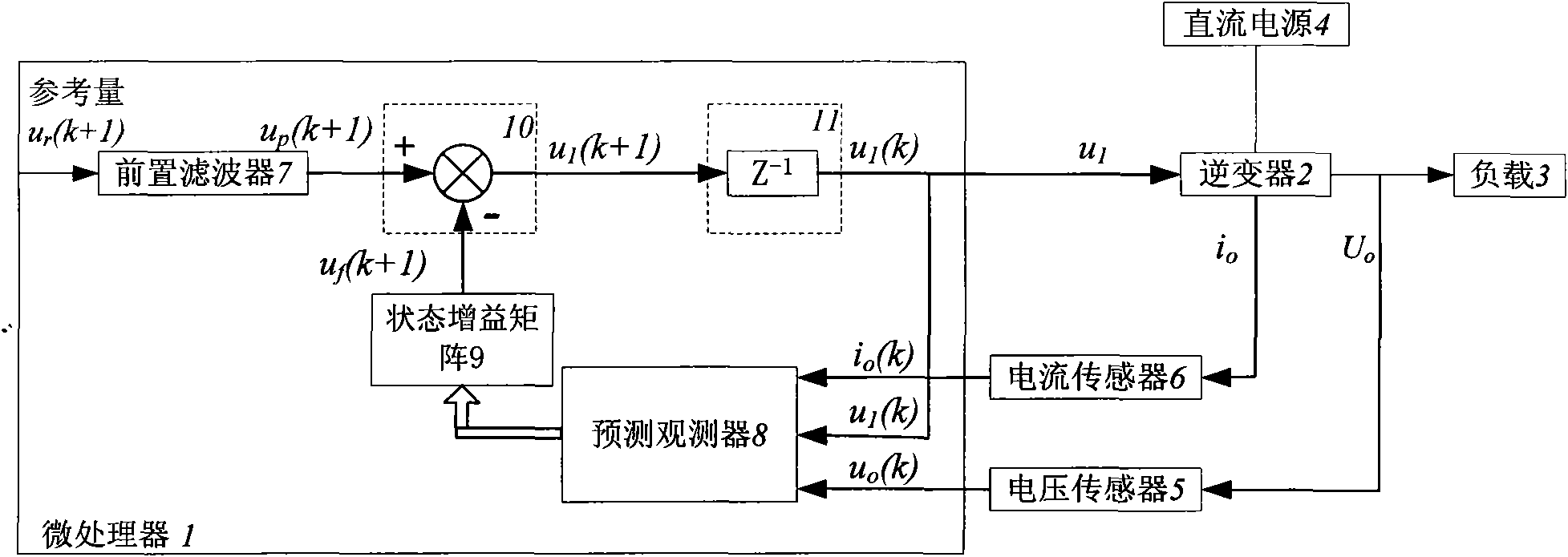
Figure 1 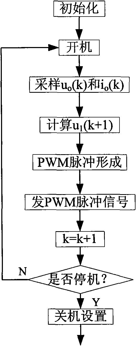
Figure 2 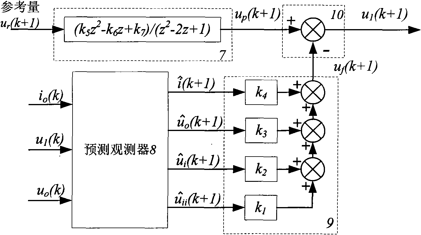
Figure 3
Abstract
Description
technical field
[0001] The invention relates to a power conversion circuit, in particular to a state tracking digital control inverter power supply. Background technique
[0002] Digital controllers can overcome the shortcomings of analog controllers such as easy aging, low versatility, and complex structure, so digital control has attracted widespread attention. With the rapid development of microelectronic technologies such as microprocessors, the application of digital control is more common. In order to give full play to the advantages of digital control, scholars at home and abroad have proposed various digital control methods.
[0003] However, the analog design of the digital controller is an indirect design, and any discretization method of the controller will have response distortion, resulting in its control performance being far inferior to that of the analog controller. In addition, repetitive control and deadbeat control, as two unique control methods of digit...
Examples
Embodiment Construction
[0019] The present invention will be described in further detail below in conjunction with the accompanying drawings.
[0020] Such as figure 1 As shown, the structure of the state tracking digital control inverter power supply provided by the present invention is:
[0021] The input terminal of the pre-filter 7 and the reference quantity u r The output end of the pre-filter 7 is connected to the positive input end of the subtractor 10 . The output terminal of the subtractor 10 is connected to the input terminal of the one-beat delay module 11 . The output terminal of the one-beat delay module 11 is connected with the control terminal of the inverter 2 and the second input terminal of the predictive observer 8 . The first input terminal of the predictive observer 8 is connected to the output terminal of the current sensor 6, the third input terminal of the predictive observer 8 is connected to the output terminal of the voltage sensor 5, and the output terminal of the predi...