
Waste organic glass continuous cracking device
A technology of plexiglass and cracking device, applied in the field of waste plexiglass continuous cracking device, can solve the problems of waste of cracking resources, high production cost, easy to cause accidents, etc., and achieve the effect of simple overall structure, control of production cost, and improvement of safety performance.
Patent Information
- Authority / Receiving Office
- CN · China
- Current Assignee / Owner
- Publication Date
- 2010-10-20
Smart Images
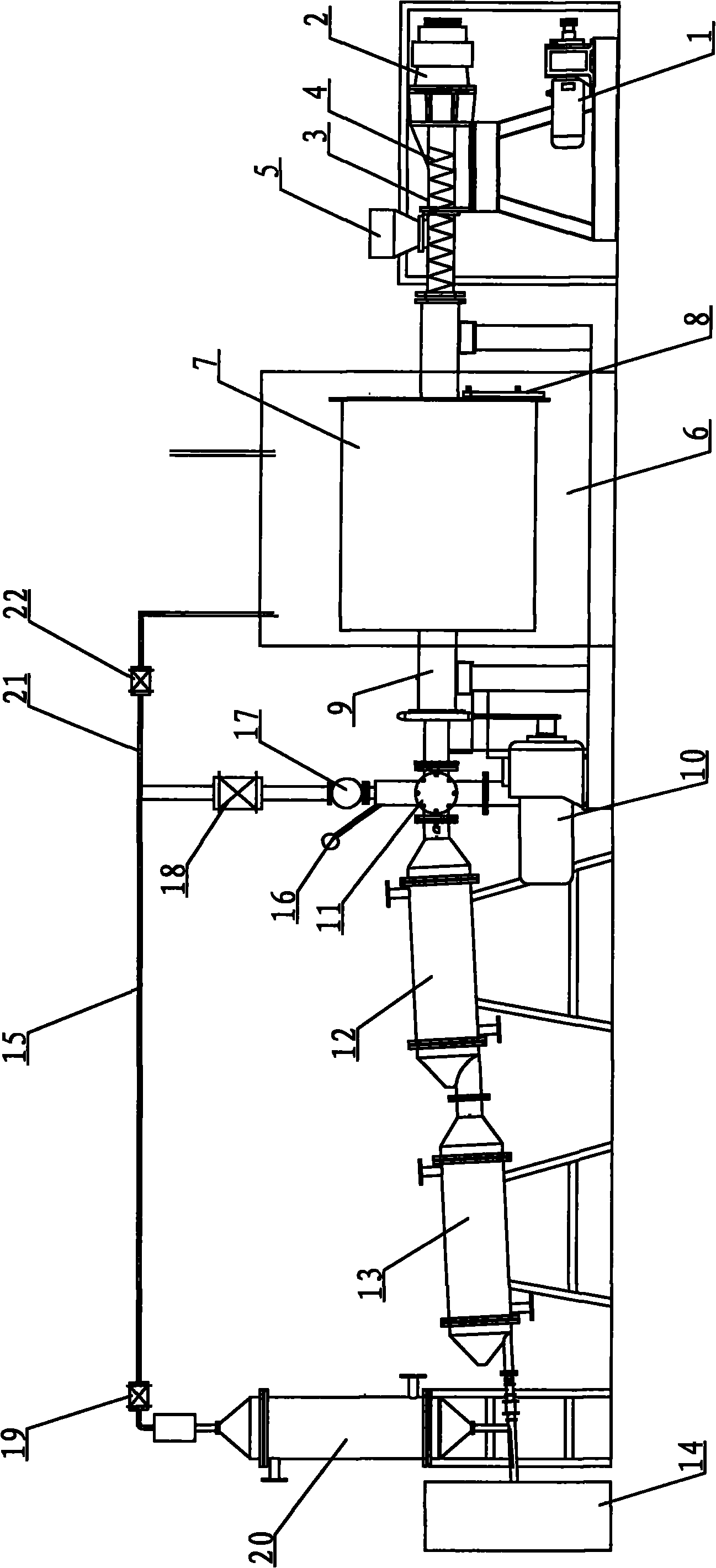
Figure 1 
Figure 2 
Figure 3
Abstract
Description
technical field
[0001] The invention relates to a cracking furnace, in particular to a waste organic glass continuous cracking device for preparing organic glass pouring raw materials. Background technique
[0002] Pyrolysis technology is one of the important means to recover and reuse various resources in the chemical industry, and cracking furnaces are often used for cracking and recycling. The traditionally used cracking furnace is mainly fed from the storage bin to the cracking bin, and is directly collected from the cooling bin after being cracked by the cracking bin. This structure can complete the whole process of resource cracking and recovery, but the gas pressure of the material in the cracking furnace after gasification Larger, if there is no safety protection device, once there is a partial failure in the cracking furnace or the air pressure is too high, it will easily cause an accident and pose a safety hazard; even if a simple pressure relief device is installe...
Examples
Embodiment Construction
[0013] The present invention will be further described below in conjunction with drawings and embodiments.
[0014] figure 1 The waste plexiglass continuous cracking device shown mainly includes a feeding device, a melting furnace and a storage tank 14 . The feeding device includes a hopper 5, a feeding pipe 3, a feeding screw 4, a reducer 2 and a feeding motor 1, one end of the feeding pipe 3 is provided with a reducer 2 connected to the feeding motor 1, and the other end of the feeding pipe 3 is connected to In a hot melting furnace, a feeding screw 4 is arranged in the feeding pipe 3, and the feeding screw 4 is connected to the reducer 2, and the feeding pipe 3 is provided with a hopper 5 located above the feeding screw 4; the hot melting furnace includes a furnace body 7, a rotating motor 10 and the incineration chamber 6, the side of the furnace body 7 is provided with a slag outlet 8, the furnace body 7 is placed in the incineration chamber 6, one end of the furnace bod...