
Signal test simulation device for testing sensor
A technology for signal testing and simulation devices, applied to measuring devices, instruments, etc., to achieve the effects of reducing complexity, reducing the introduction of error signals, and facilitating data playback
Patent Information
- Authority / Receiving Office
- CN · China
- Current Assignee / Owner
- Publication Date
- 2012-02-01
Smart Images
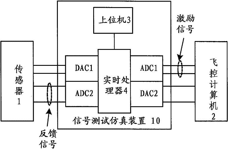
Figure 1 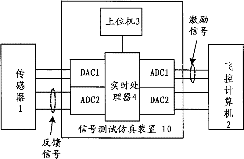
Figure 2
Abstract
Description
technical field
[0001] The invention relates to a signal test simulation device, in particular to the test and simulation of sensor signals applied in a flight control system. Background technique
[0002] LVDT (Linear Variable Differential Transformer) or RVDT (Rotary Variable Differential Transformer) sensors are widely used in fly-by-wire flight control systems due to their high precision, stable performance, and easy integration. The displacement is sent to the flight control computer, which calculates the control rate and then controls the terminal's actuating mechanism to actually control the aircraft. As the input of the entire flight control system, the sensor is very important in the function verification test and data analysis of the flight control system. Therefore, the test of the sensor itself has become a topic. At present, the test method for this type of sensor itself is to pass the sensor signal through a dedicated signal conditioning board, which will cond...
Examples
Embodiment Construction
[0011] As shown in Figure 1, the signal test simulation device 10 for testing the sensor 1 is connected in series between the differential transformer sensor 1 and the flight control computer 2, and it includes a host computer 3, a real-time processor 4, a first modulus Converter ADC1, first digital-to-analog converter DAC1, second analog-to-digital converter ADC2 and second digital-to-analog converter DAC2, real-time processor 4 and upper computer 3, first analog-to-digital converter ADC1, first digital-to-analog converter The device DAC1, the second analog-to-digital converter ADC2 and the second digital-to-analog converter DAC2 are respectively electrically connected; wherein, the excitation signal sent by the flight control computer 2 passes through the first analog-to-digital converter ADC1, the real-time processor 4 and the first digital-to-analog converter successively. The analog converter DAC1 is sent to the sensor 1, and the excitation signal sent by the flight contro...