
Hysteresis massager
A massager and hysteresis technology, which is applied in the field of hysteresis massagers, can solve the problems of difficult sealing of the main basin, complex production process, and high production cost, and achieve the effects of convenient overall layout, simple production process, and low production cost
Patent Information
- Authority / Receiving Office
- CN · China
- Patent Type
- Applications(China)
- Current Assignee / Owner
- Publication Date
- 2012-07-11
- Estimated Expiration
- Not applicable · inactive patent
Smart Images
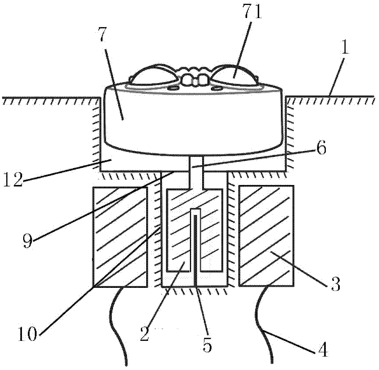
Figure 1 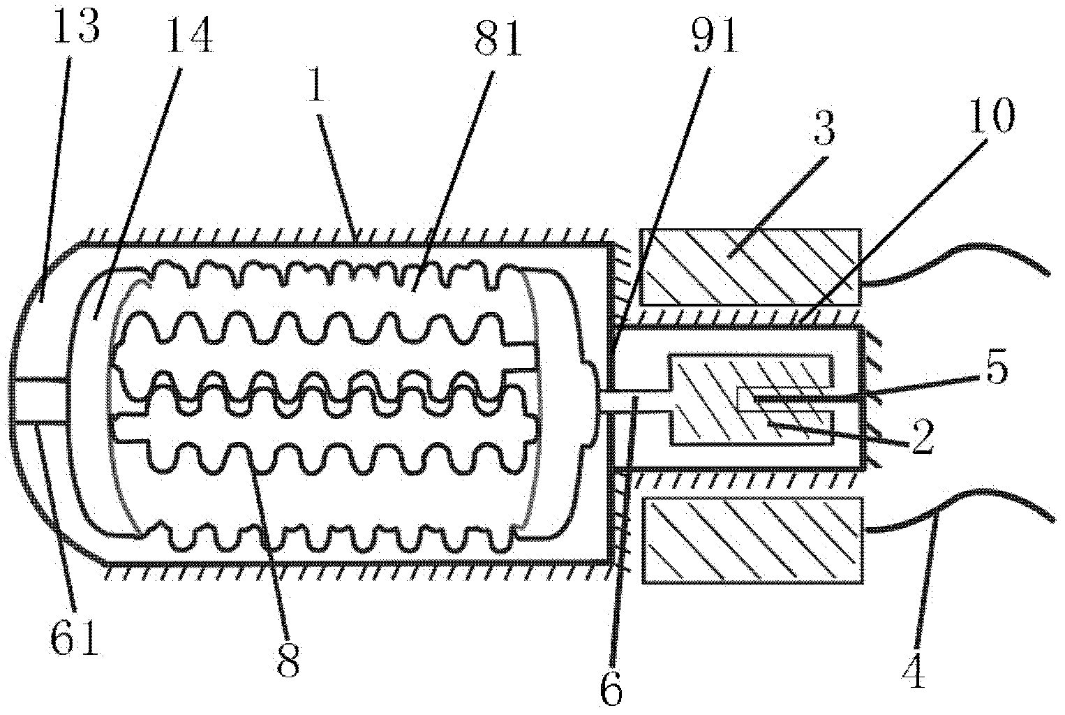
Figure 2 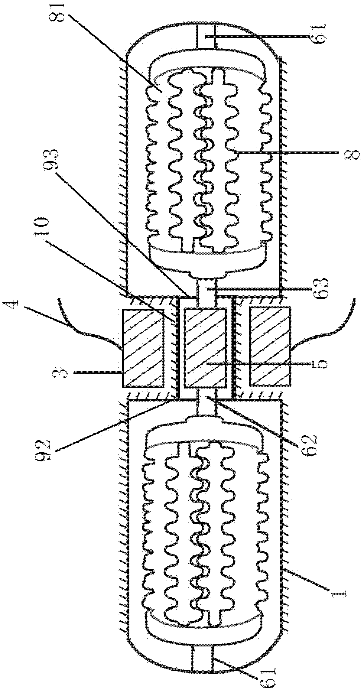
Figure 3
Abstract
Description
Technical field
[0001] The invention relates to a health-care appliance, in particular to a hysteresis massager which utilizes the hysteresis phenomenon for health care or physical therapy. Background technique
[0002] At present, most massagers use mechanical transmission mechanisms such as motors and transmission boxes to achieve power transmission. Due to the presence of intermediate transmission components such as transmission boxes, there are many parts, complex structures, complex production processes and production. high cost. In addition, the motor as a power source must work in a working environment isolated from water. For example, the motor of a foot massager must be placed outside the main basin, and the shaft of the massage head must pass through the main basin. There is water, which brings great difficulties to the sealing of the main basin. If it is not handled well, it will cause safety accidents due to water leakage. Summary of the invention
[0003] In order t...
Examples
Embodiment Construction
[0026] Such as figure 1 Example one shown. The hysteresis massager includes a main basin 1, a massage head and a driving mechanism for driving the massage head.
[0027] The driving mechanism includes a magnetic core rotor 2 located in the main basin 1 and a coil 3 located in the interlayer outside the main basin. The main basin 1 is provided with a rotor chamber 10 that accommodates the magnetic core rotor and is matched with the magnetic core rotor 2, and the rotor chamber 10 is a cylindrical chamber. The magnetic core rotor 2 is a columnar body containing magnets or magnetizable materials. One end of the core rotor is axially provided with a rotor center hole, an axial center positioning shaft 5 fixed on the rotor chamber 10 is placed in the rotor center hole, and the center positioning shaft 5 has a positioning function for the core rotor 2. In order to reduce the frictional resistance of the rotor, the partial friction caused by the eccentricity of the magnetic core rotor ...