
Corner flattening mechanism for framing machine
A framing machine and corner technology, which is applied in sustainable manufacturing/processing, electrical components, climate sustainability, etc., can solve the problems of damage to the corners of solar modules, bulky machine appearance, and not beautiful enough to achieve beautiful appearance and high durability. Even force, better effect
Patent Information
- Authority / Receiving Office
- CN · China
- Current Assignee / Owner
- Publication Date
- 2013-01-16
- Estimated Expiration
- Not applicable · inactive patent
Smart Images
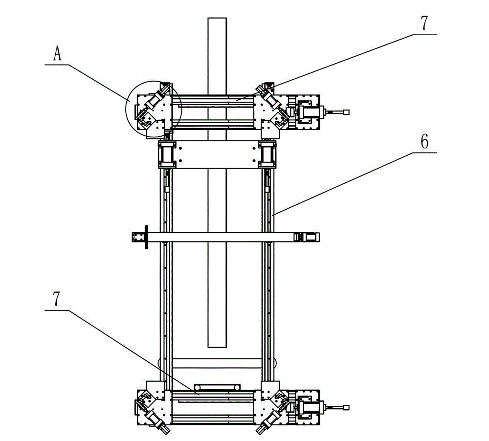
Figure 1 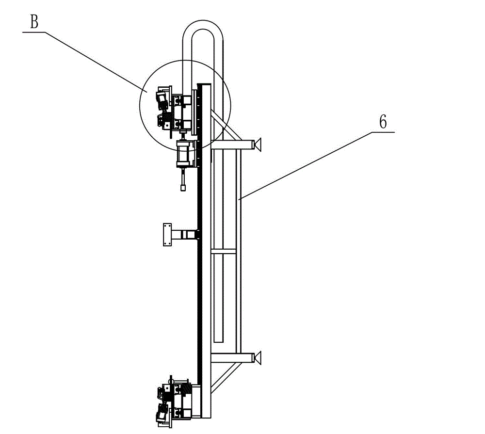
Figure 2 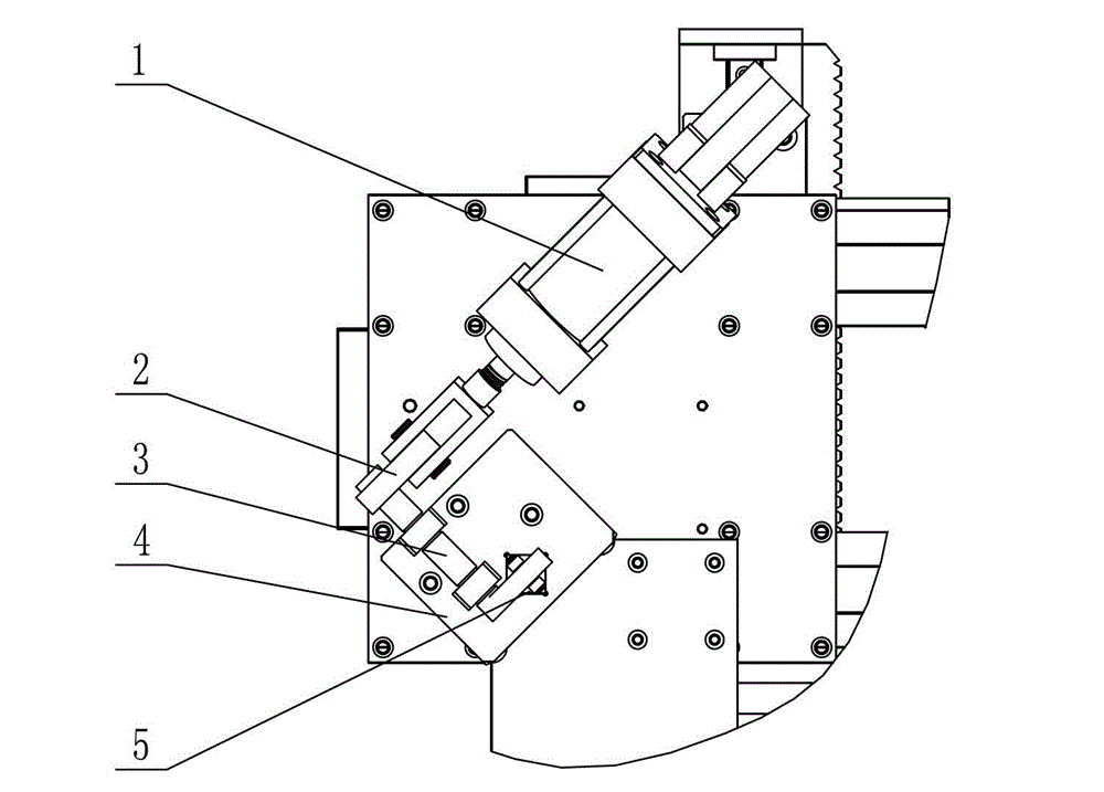
Figure 3
Abstract
Description
technical field
[0001] The invention relates to a flattening mechanism at the corner of a framing machine, in particular to a flattening device on a solar battery module framing machine. Background technique
[0002] The solar photovoltaic industry is currently an emerging sunrise industry. The solar cell module framing machine is a device for assembling solar panels on an automatic transmission line, which can improve the work efficiency of solar module framing. At present, the corner flattening device of the solar cell module framing machine generally uses a cylinder to directly flatten the corner. The cylinder is relatively large, and the appearance of the machine is large and complicated, and it is not beautiful enough. In addition, the cylinder of the existing flattening device adopts a direct downward flattening operation, which is easy to cause damage to the four corners of the solar module. Contents of the invention
[0003] The purpose of the present invention is...
Examples
Embodiment Construction
[0011] The present invention will be further described below in conjunction with specific drawings.
[0012] Such as Figure 1 ~ Figure 4 As shown: the corner flattening mechanism of the framing machine includes a pressing cylinder 1, a connecting arm 2, a rotating lever 3, a rotating pressing block 4, a connecting seat 5, a framing machine 6, and the like.
[0013] Such as image 3 , Figure 4 As shown, the present invention includes a compression cylinder 1 installed at the four corners of the framing machine 6, the piston rod of the compression cylinder 1 is rotatably connected to one end of the connection arm 2, and the other end of the connection arm 2 is connected to the rotary lever 3 One end of the rotary lever 3 is connected with the connecting seat 5, and the connecting seat 5 is rotationally connected with the rotary briquetting block 4, and the bottom of the connecting seat 5 is slidably matched with the rotary briquetting block 4.
[0014] Such as figure 1 , ...