
A floating pressing roller and a winding machine comprising the floating pressing roller
A technology of pressing roller and frame, which is applied in the field of textile and chemical fiber machinery, can solve the problems of poor parallelism of two bobbin chuck axes, finishing of winding machine, difficulty of assembly, debugging and maintenance, etc., and achieve good contact effect
Patent Information
- Authority / Receiving Office
- CN · China
- Patent Type
- Patents(China)
- Current Assignee / Owner
- Publication Date
- 2015-08-05
Smart Images
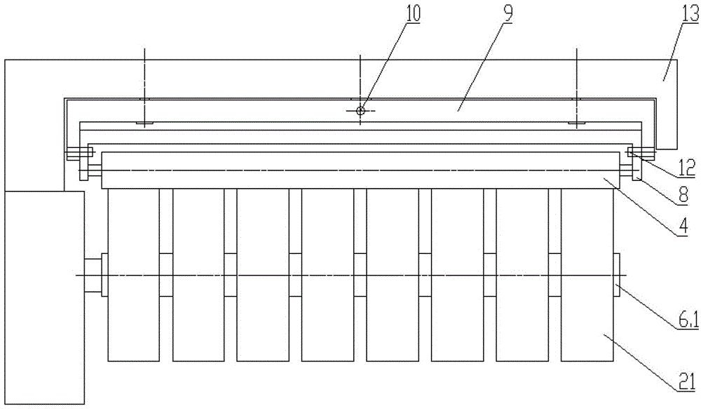
Figure 1 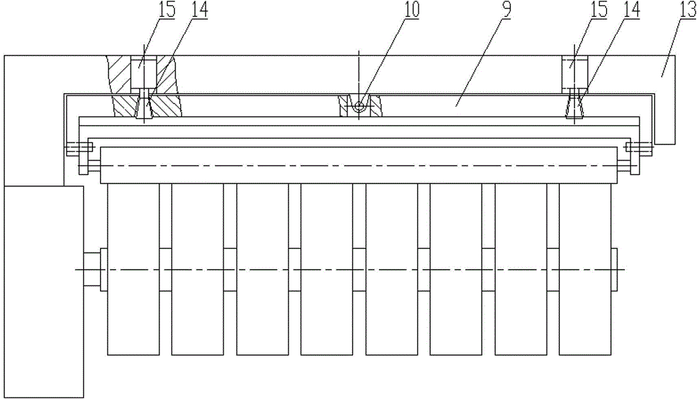
Figure 2 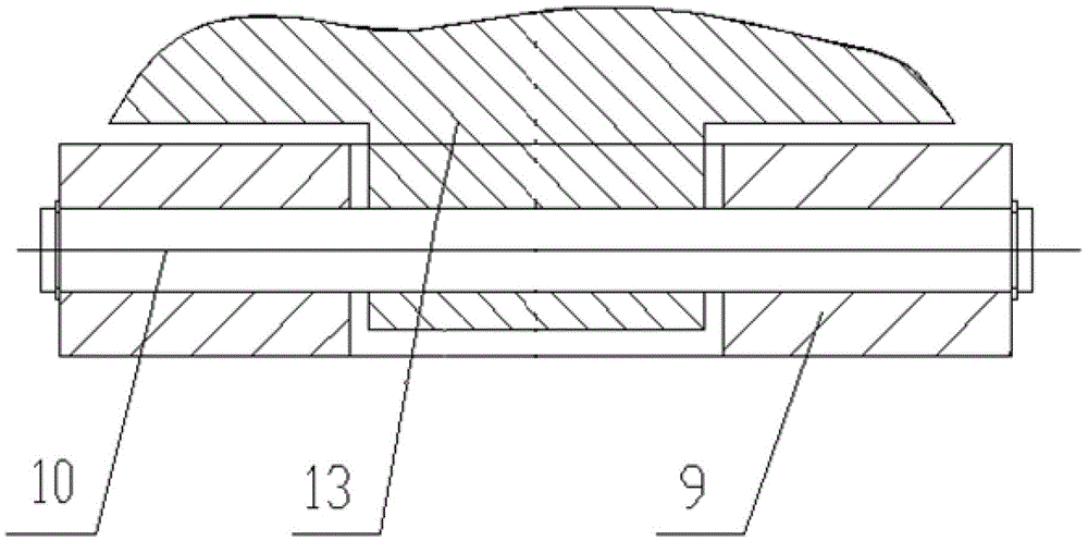
Figure 3
Abstract
Description
technical field
[0001] The invention relates to the field of textile and chemical fiber machinery, in particular to a floating pressing roller and a winding machine comprising the floating pressing roller. Background technique
[0002] The chemical fiber filament winding machine is used for continuous winding of filaments. A rotatable turntable is installed in the frame of the automatic winding machine, and two protruding rotatable bobbin chucks are mounted on the cantilever on the turntable. Shaft, each bobbin chuck shaft is equipped with a plurality of paper bobbin tubes, a pressing roller is installed above the working bobbin chuck shaft, and a traversing device is arranged above the pressing roller.
[0003] During a winding cycle, the wire pressing roller contacts with the circumference of the silk cake being formed on the working bobbin chuck shaft with a certain pressure, and the rotation of the turntable makes the pressure roller and the working bobbin chuck shaft co...
Examples
Embodiment Construction
[0029] see figure 1 and figure 2 As shown, the floating pressing roller provided by the embodiment of the present invention includes a second bracket 8 and a first bracket 9, and the left and right ends of the pressing roller 4 are rotatably mounted on the two arms of the second bracket 8 through bearings. Inside, the two arms of the second bracket 8 are formed by bending the left and right ends of the second bracket 8 . The second bracket 8 is installed on the two arms of the first bracket 9 through pin shafts 12 , wherein the two arms of the first bracket 9 are formed by bending the left and right ends of the first bracket 9 . Such as image 3 As shown, the first bracket 9 is connected to the frame 13 through a shaft.
[0030] see figure 2 , at the left and right ends of the first bracket 9, two locking pins 14 are installed. The locking end of the locking pin 14 is movably connected with the first bracket 9 through the hole provided on the first bracket 9, and the ot...