
Automatic spraying-control device for coal-conveying belt in mine shaft
A spray control and belt technology, applied in the direction of conveyor control devices, transportation and packaging, conveyor objects, etc., can solve life-threatening and production safety, affect workers' health, environmental pollution and other problems, achieve reasonable structure, simple implementation, cleverly conceived effects
Patent Information
- Authority / Receiving Office
- CN · China
- Current Assignee / Owner
- Publication Date
- 2013-07-10
- Estimated Expiration
- Not applicable · inactive patent
Smart Images
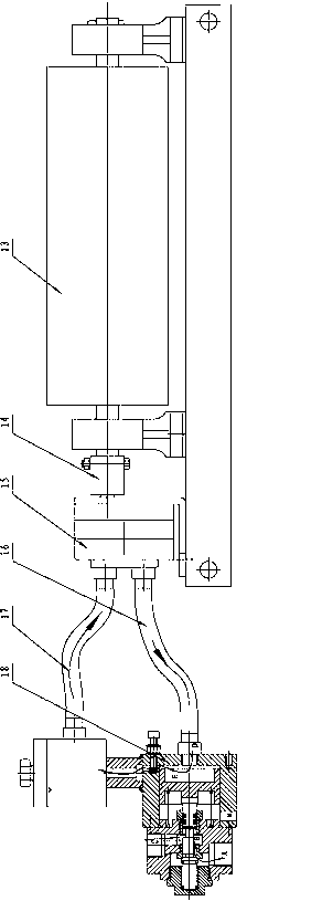
Figure 1 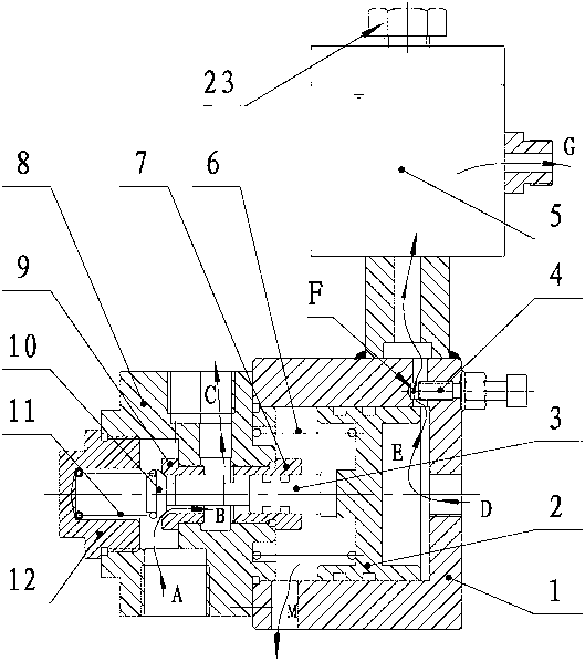
Figure 2 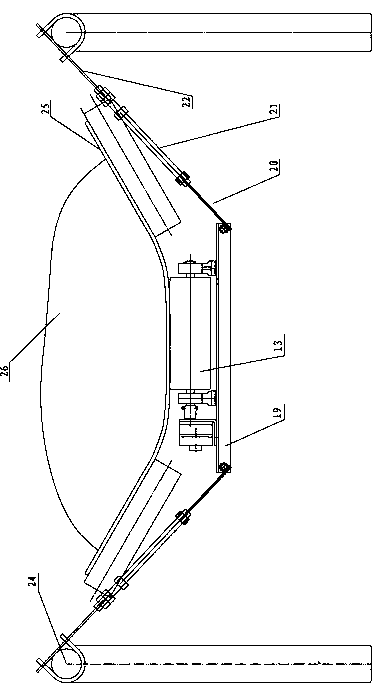
Figure 3
Abstract
Description
[0001] technical field
[0002] The invention relates to a spray control device, in particular to an automatic spray control device for a coal conveying belt in a mine, which is used to prevent dust from flying and needs to be sprayed when the belt conveys granular materials (such as coal, stone, sand, etc.). It belongs to the technical field of mine equipment. Background technique
[0003] From the physical properties of dust and the basic laws of its movement, as long as there is relative movement between dust and air, it may cause dust to fly. Dust not only affects normal production and the health of workers, but also causes environmental pollution. In severe cases, it may cause dust explosion, endangering life and production safety.
[0004] For material transportation that can be sprayed with water, the simple and effective way to prevent dust flying is to spray. How to carry out timely, appropriate and effective spraying is the most concerned technical issue in the p...
Examples
Embodiment Construction
[0021] Please refer to the manual attached figure 1 to the attached image 3 As shown, the present invention is an automatic spray control device for coal conveying belts in mines, which consists of friction rollers 13, coupling sleeves 14, gear pumps 15, oil inlet pipes 16, oil outlet pipes 17 and controller 18.
[0022] Wherein, the gear pump 15 is linked to the friction roller 13 through the connecting sleeve 14; the oil inlet pipe 16 and the oil outlet pipe 17 are respectively connected to the gear pump 15; the controller 18 is respectively connected to the oil inlet pipe 16, Outlet pipe 17.
[0023] Further, the controller 18 includes a piston cylinder 1, a piston 2, a push rod 3, a pressure regulating screw 4, an oil storage tank 5, a piston spring 6, a push rod guide nut 7, a water inlet and outlet seat 8, and a valve core nut 9 , Guide spool 10 , spool spring 11 and end cap nut 12 . The piston 2 and the piston spring 6 are loaded into the piston cylinder 1 from the ...