
Internal reflective vacuum heat collector, forming device and close-packed heat collector
A vacuum heat collecting tube and forming device technology, which is applied in heating devices, solar thermal devices, forming tools, etc., can solve the problems of large heat capacity, light leakage, and water storage in heat collecting tubes, and achieve the effect of small heat capacity
Patent Information
- Authority / Receiving Office
- CN · China
- Patent Type
- Patents(China)
- Current Assignee / Owner
- Publication Date
- 2015-11-04
- Estimated Expiration
- Not applicable · inactive patent
Smart Images
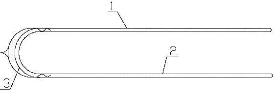
Figure 1 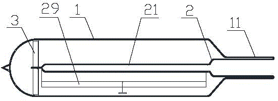
Figure 2 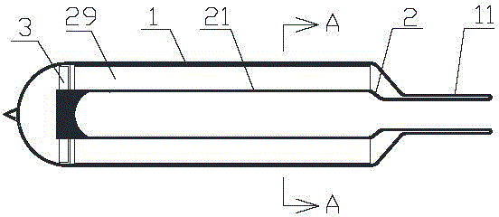
Figure 3
Abstract
Description
technical field
[0001] The invention relates to a device in the field of solar photothermal technology, in particular to an internal reflective vacuum heat collecting tube for a solar water heater, a molding device and a densely packed heat collector. Background technique
[0002] Solar water heaters convert sunlight energy into thermal energy and heat water from low temperature to high temperature to meet the hot water needs in people's lives. Solar water heaters are divided into vacuum tube solar water heaters and flat plate solar water heaters according to their structure. The vacuum tube solar water heater is composed of vacuum heat collecting tubes, water storage tanks and brackets and other related components. The conversion of solar energy into heat mainly depends on the heat collecting tubes. hot water. Such as figure 1 As shown, the general glass heat collecting tube is composed of an equal-diameter glass inner tube 2 and an equal-diameter glass outer tube 1. A v...
Examples
Embodiment Construction
[0042] Such as figure 2 , image 3 with Figure 4 As shown, an internally reflective vacuum heat collecting tube of the present invention includes an outer tube 1, an inner tube 2 and a retaining spring 3, the inner tube 2 fits inside the outer tube 1, and the outer surface of the inner tube is coated with non- White selective light-to-heat conversion coating, the circlip 3 is arranged between the outer tube 1 and the inner tube 2 and is located at the tail end of the inner tube 2, the top ends of the outer tube 1 and the inner tube 2 are welded and sealed, and the outer The interlayer between the tube 1 and the inner tube 2 is a vacuum, and also includes a reflector 29. The diameter of the front section of the outer tube 1 is smaller than the diameter of the rear section to form a reduced diameter section 11, and the inner tube 2 is in the corresponding reduced diameter section of the outer tube 1. Below 11 is a flat tube 21, the reflector 29 is arranged in the interlayer ...