
Two-way positioning plug-in preform holder push mechanism
A technology of two-way positioning and pushing mechanism, applied in the field of bottle blowing machines, can solve problems such as inaccessibility of preforms, complex structure, and inability of preform holders to correspond to blowing molds, etc.
Patent Information
- Authority / Receiving Office
- CN · China
- Patent Type
- Patents(China)
- Current Assignee / Owner
- Publication Date
- 2015-09-02
Smart Images
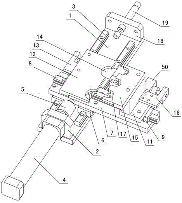
Figure 1 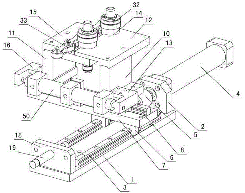
Figure 2 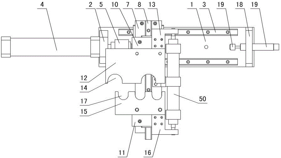
Figure 3
Abstract
Description
technical field
[0001] The invention relates to a bottle blowing machine, in particular to a two-way positioning plate type preform seat pushing mechanism of the bottle blowing machine. Background technique
[0002] Plastic raw materials such as PET are used to process them into hollow containers such as mineral water bottles and oil bottles through injection stretch blowing. First, the plastic raw materials are injected into preforms by injection molding machine. The machine stretches and blows the heated preform. The conveyor chain in the heating tunnel of the existing equipment is driven by the servo motor to rotate the gear, and the gear drives the conveyor chain to run. The disadvantage of this structure is: when the voltage is unstable, it is easy to cause the servo motor speed to be inaccurate, so that the motor installed on the conveyor chain The preform seat on the top cannot correspond to the blowing mold, so that the preform cannot enter the blowing mold, and the...
Examples
Embodiment Construction
[0012] The invention relates to a two-way positioning plug-in type bottle base seat pushing mechanism, such as figure 1 — Figure 5 As shown, it is characterized in that: it includes a machine base, a stepping base plate 1 is arranged on the machine base, a cylinder fixing plate 2 and a left and right slide rail 3 are installed on the stepping base plate, and a push cylinder 4 is installed on one side of the cylinder fixing plate 2, and the push cylinder The piston rod is connected to the floating joint 5, and the left and right sliding blocks 6 are arranged on the left and right slide rails 3, and the left and right moving slide plates 7 are installed on the left and right moving slide blocks, and the left and right moving slide plates are connected with the floating joint 5, and the front and rear slide rails 8 are installed on the left and right moving slide plates , the front and rear moving sliders 9 are set on the front and rear slide rails, the front and rear slides 10 ...