
Multi-gear driving device of hybrid power vehicle
A hybrid vehicle and driving device technology, applied in the direction of hybrid vehicles, power devices, pneumatic power devices, etc., can solve the problems of limited single-motor working mode, slip loss, and limited vehicle performance, etc., to achieve The driving form is flexible, the power is good, and the smoothness is good
Patent Information
- Authority / Receiving Office
- CN · China
- Patent Type
- Applications(China)
- Current Assignee / Owner
- Publication Date
- 2014-06-18
Smart Images
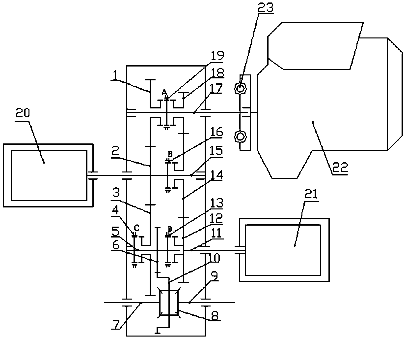
Figure 1 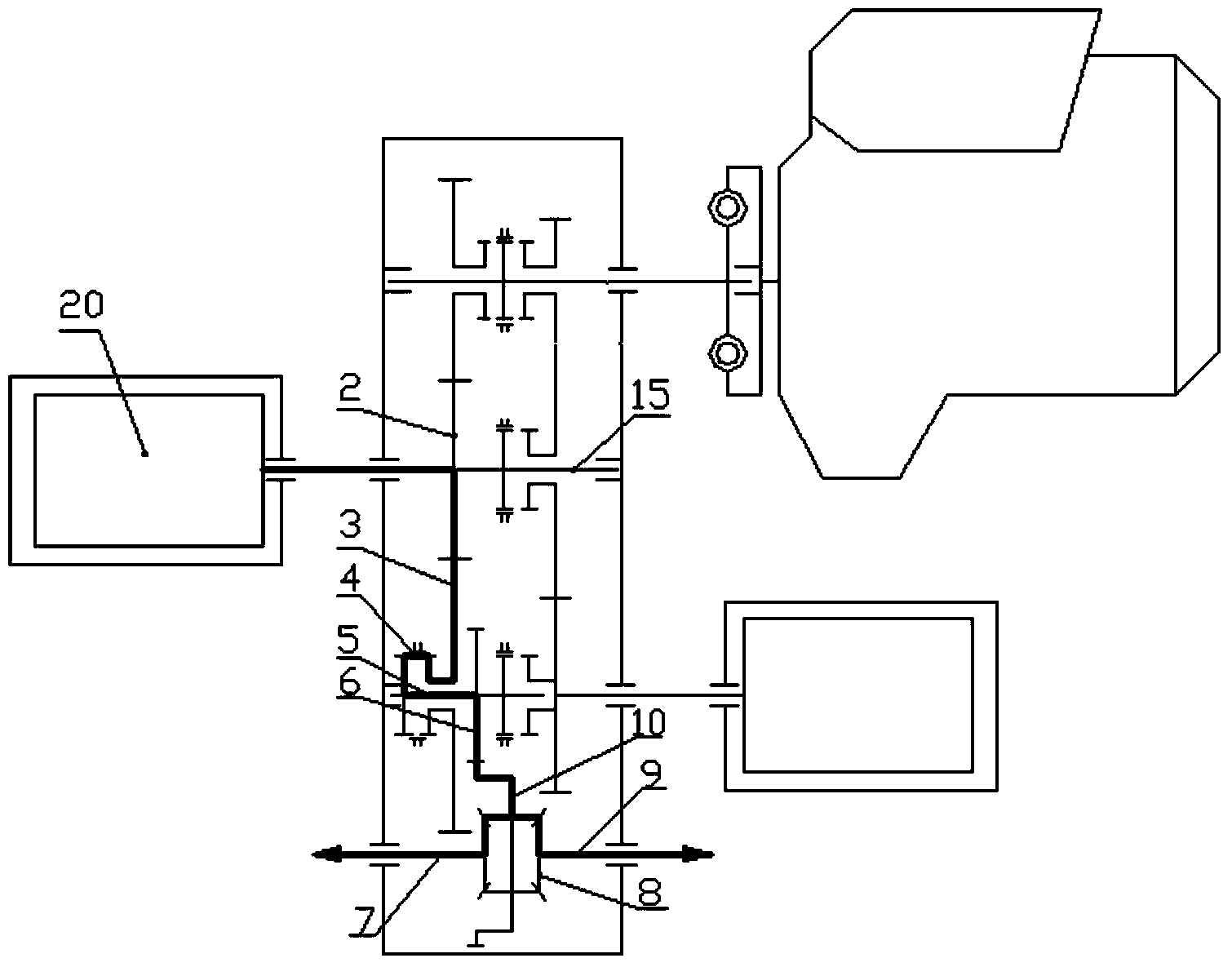
Figure 2 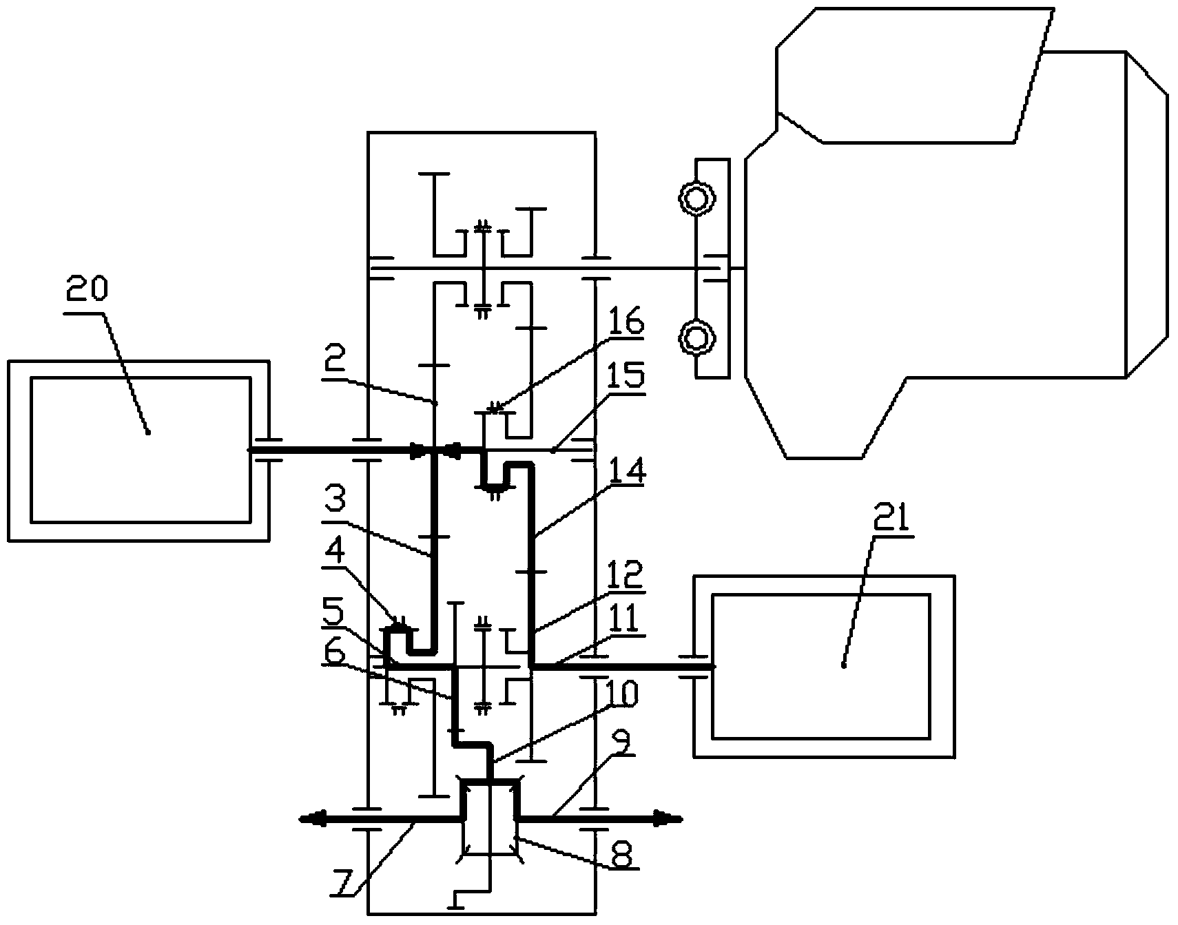
Figure 3
Abstract
Description
Technical field
[0001] The invention relates to the technical field of hybrid power vehicle transmission, in particular to a hybrid power vehicle multi-gear drive device. technical background
[0002] Today's automobile industry is facing tremendous pressure. With energy shortages and air pollution becoming more and more serious, various auto companies have launched energy-saving and environmentally friendly cars. Including pure electric vehicles and hybrid vehicles. Restricted by battery technology and charging technology, the driving range of pure electric vehicles cannot meet the needs of long-distance driving, and the requirements for supporting infrastructure such as charging stations are relatively high.
[0003] Compared with pure electric vehicles, hybrid vehicles do not need to change the infrastructure, can meet the requirements of long-distance driving, have less pollution, and the technology is relatively mature. It has become the best choice for auto companies to sol...
Examples
Embodiment 2
[0093] As an improved scheme of a hybrid vehicle multi-gear drive device provided by the present invention, if one more gear Ⅶ24 is connected to the transmission input shaft I15 of the aforementioned scheme, the idler gear Ⅷ25 on the driven shaft 5, such as Figure 7 As shown, gear Ⅶ24 and gear Ⅷ25 form a pair of meshing teeth. Gear Ⅶ24 is fixedly connected to the transmission input shaft I15 and is located between gear III2 and the coupling sleeve B16. Gear Ⅷ25 is empty sleeved on the driven shaft 5 and located in the coupling sleeve C4 and Combine between sets of D13. Similarly, the coupling sleeve C4 controls the engagement and disengagement of the gear Ⅷ25 and the driven shaft 5. In this way, on the basis of the original invention, the gears of the motor Ⅰ 20 and the motor Ⅱ 21 are increased by one, and the gear of the engine 22 is increased by two. , It is more beneficial for the engine 22 and the electric motor I 20 and the electric motor II 21 to work in the high-efficien...