
Capping machine claw head
A technology of capping machine and claw head, which is applied in the field of capping machine claw head, can solve the problems of complex design, insufficient equipment optimization, complex mechanism design, etc., and achieve the effect of simplified design, excellent overall machine and reduced cost
Patent Information
- Authority / Receiving Office
- CN · China
- Patent Type
- Patents(China)
- Current Assignee / Owner
- Publication Date
- 2017-02-15
Smart Images
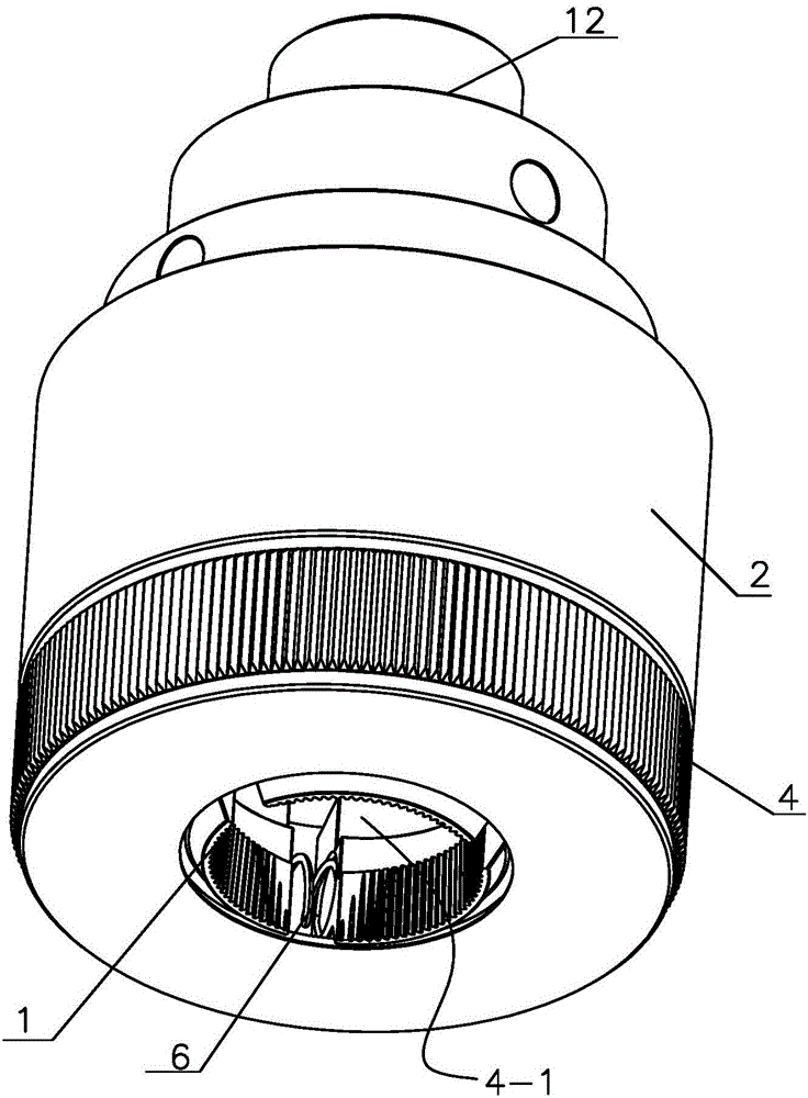
Figure 1 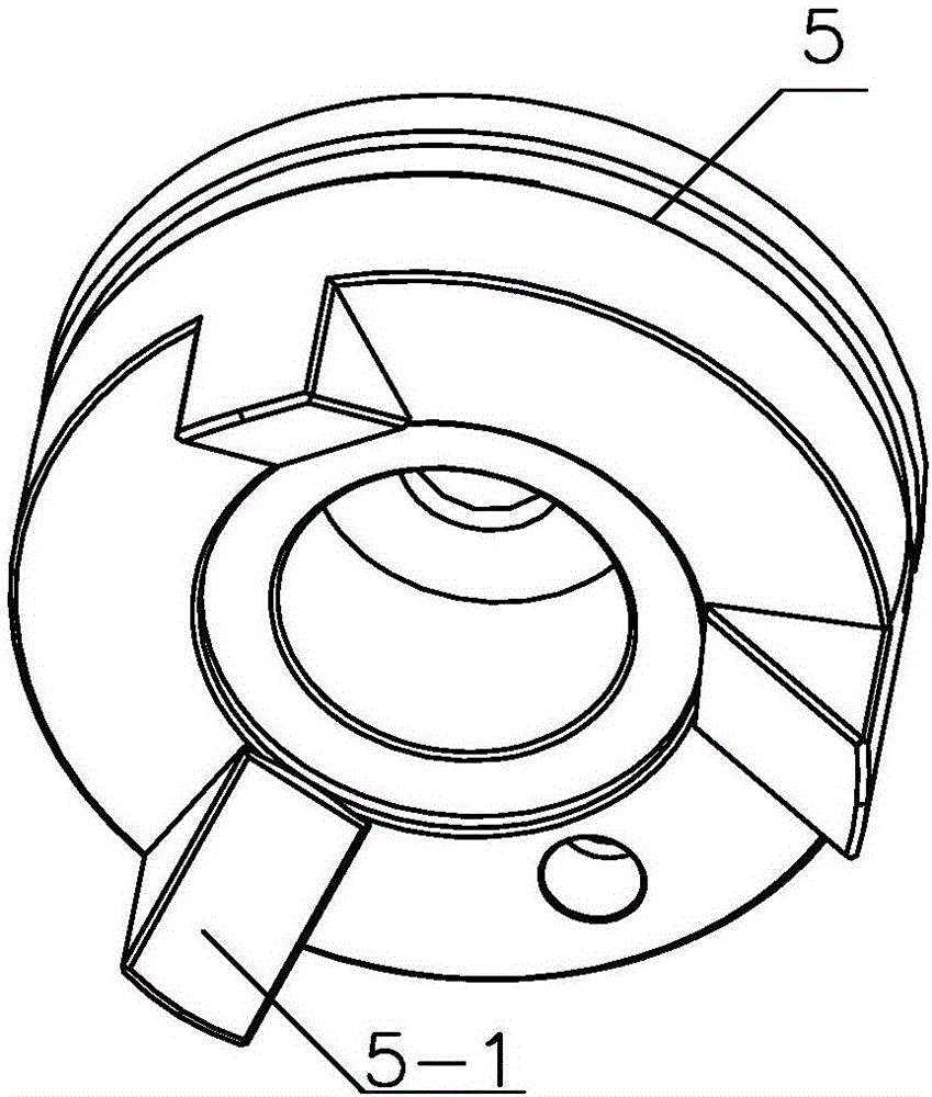
Figure 2 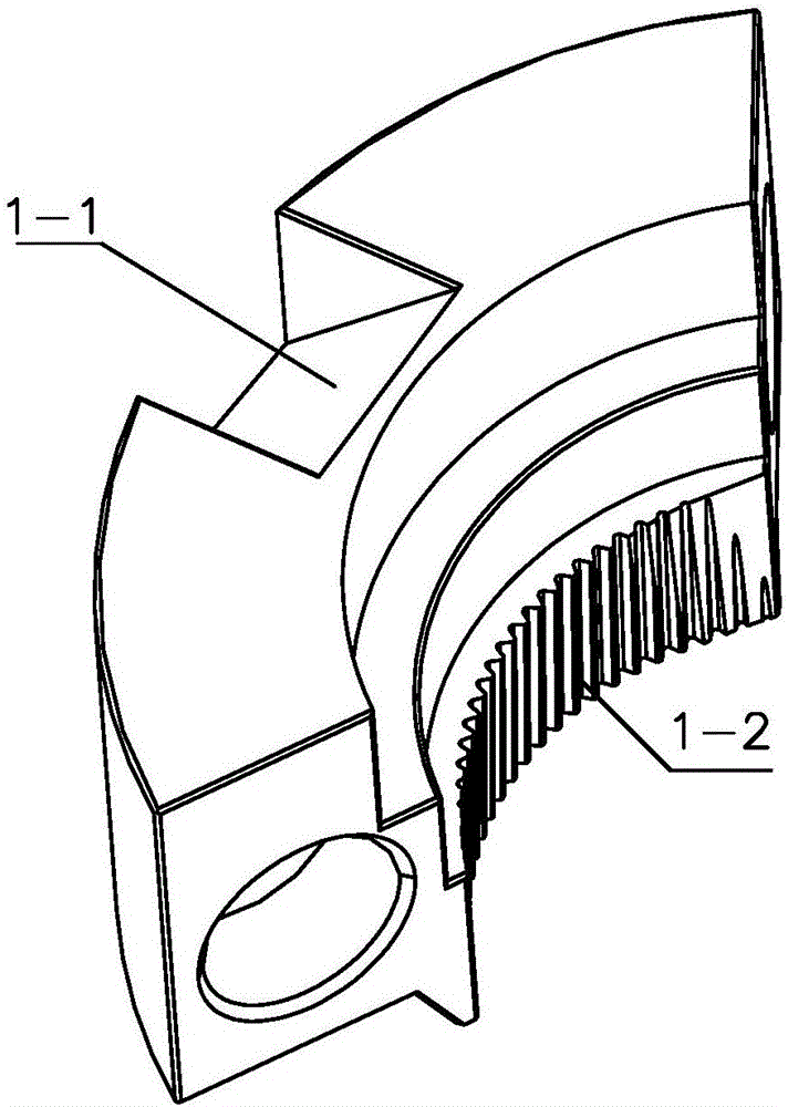
Figure 3
Abstract
Description
technical field
[0001] The invention relates to the technical field of capping machines, in particular to provide a fast and reliable claw head of the capping machine for the capping machine's structure of grasping caps. Background technique
[0002] The automatic capping machine is a device that can screw the cap on the bottle body. It is widely used in daily chemical, food, medicine and other industries. Its structure generally includes a frame, a power transmission device and a capping assembly. There is a rotating part in the cap assembly, and the power device drives the rotating part to rotate. The bottle cap is stuck in the chuck of the rotating part. With the rotation of the rotating part, the bottle cap is tightened on the bottle body. It is a claw structure. For example, application number 201210474244.4 discloses a capping device on a capping machine. The capping device uses a push rod to push the claws to achieve opening and tightening. Although it can also grasp ...
Examples
Embodiment 1
[0032] Such as Figure 4 , the claw seat 2 has an inner cavity, the bottom of the claw seat 2 is equipped with a claw cover seat 4, the center of the claw cover seat 4 has a bottle cap inlet 4-1, and several claws 1 evenly surround the inner cavity of the claw seat 2 and are placed on the claw cover seat 4 on;
[0033] Such as figure 2 image 3 , the pusher 3 includes a piston 5, the outer ring of the piston 5 is in sealing and sliding contact with the inner cavity of the claw seat 2, the bottom surface of the piston 5 is provided with the same number of wedges 5-1 as the number of claws 1, and each claw 1 is provided with a chute 1 -1, the wedge 5-1 on the bottom surface of the piston 5 is correspondingly inserted into the chute 1-1;
[0034] The inclination direction of the wedge 5-1 and the chute 1-1 is upwardly inclined from the outside to the inside, and the surrounding claws 1 are connected with the claws 1 by a compression spring 6 .
[0035]It also has a pin 7 and...
Embodiment 2
[0037] Such as Figure 5 , the claw seat 2 has an inner cavity, the bottom of the claw seat 2 is equipped with a claw cover seat 4, the center of the claw cover seat 4 has a bottle cap inlet 4-1, and several claws 1 evenly surround the inner cavity of the claw seat 2 and are placed on the claw cover seat 4 on;
[0038] Such as figure 2 image 3 , the pusher 3 includes a piston 5, the outer ring of the piston 5 is in sealing and sliding contact with the inner cavity of the claw seat 2, the bottom surface of the piston 5 is provided with the same number of wedges 5-1 as the number of claws 1, and each claw 1 is provided with a chute 1 -1, the wedge 5-1 on the bottom surface of the piston 5 is correspondingly inserted into the chute 1-1;
[0039] The inclination direction of the wedge 5-1 and the chute 1-1 is upwardly inclined from the outside to the inside, and the surrounding claws 1 are connected with the claws 1 by a compression spring 6 .
[0040] There is also a pin sh...
Embodiment 3
[0042] Such as Image 6 , the claw seat 2 has an inner cavity, the bottom of the claw seat 2 is equipped with a claw cover seat 4, the center of the claw cover seat 4 has a bottle cap inlet 4-1, and several claws 1 evenly surround the inner cavity of the claw seat 2 and are placed on the claw cover seat 4 on;
[0043] Such as figure 2 image 3 , the pusher 3 includes a piston 5, the outer ring of the piston 5 is in sealing and sliding contact with the inner cavity of the claw seat 2, the bottom surface of the piston 5 is provided with the same number of wedges 5-1 as the number of claws 1, and each claw 1 is provided with a chute 1 -1, the wedge 5-1 on the bottom surface of the piston 5 is correspondingly inserted into the chute 1-1;
[0044] The inclination direction of the wedge 5-1 and the chute 1-1 is upwardly inclined from the outside to the inside, and the surrounding claws 1 are connected with the claws 1 by a compression spring 6 .
[0045] It also has pin shaft 7...