
Composite screw transporting vehicle
A transport vehicle and screw technology, applied in the direction of sales of raw material supply devices, clay preparation devices, unloading devices, etc., can solve the problems of difficult cleaning and cleaning, uneven mixing, easy to leak, etc., to improve cleaning efficiency, Improve the uniformity of mixing, avoid leakage and odor loss
Patent Information
- Authority / Receiving Office
- CN · China
- Patent Type
- Applications(China)
- Current Assignee / Owner
- Publication Date
- 2015-03-04
Smart Images
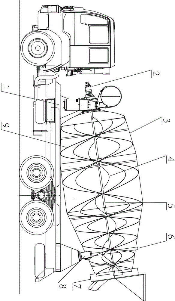
Figure 1 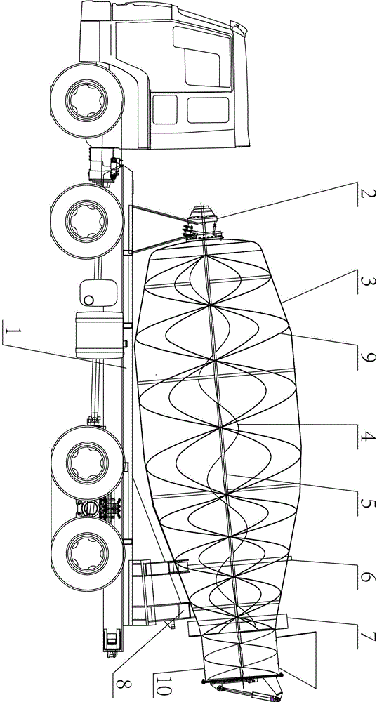
Figure 2
Abstract
Description
technical field
[0001] The invention relates to a cargo transport vehicle, which is mainly used for transporting concrete or sludge. Background technique
[0002] Because of its high viscosity and low fluidity, the transfer cost of sludge as industrial waste or domestic waste is relatively high. Since there is no special vehicle suitable for sludge transportation on the market, the current sludge transportation generally relies on self-unloading freight vehicles, and adopts mechanical or manual methods, or cooperates with special cleaning devices to carry out sludge loading and unloading. . The main disadvantages of the current sludge transportation methods are: first, it is difficult to load and the compartment is difficult to be fully loaded; second, it is difficult to discharge the material, and it is difficult to clean it when unloading; 1. It is very difficult to wash and clean, and it is poisonous; 4. The compartment is not well sealed, and it is easy to leak and...
Examples
Embodiment 1
[0021] Such as figure 1 , this embodiment includes a vehicle frame 1 and a rotating material cylinder 3 rotatably seated on the vehicle frame 1 through a slewing bracket 8. The front end of the rotating material cylinder 3 is equipped with a power assembly 2 for driving the rotating material cylinder 3 to rotate. The rear end of the barrel 3 is connected with a feed port and a discharge port through a rotary sealing mechanism 7 . A rotary track 6 is installed on the outer wall of the rotating barrel 3 . The main blade 9 in the form of a spiral is installed on the inner wall of the rotating barrel 3 .
[0022] The rotary sealing mechanism 7 includes a rotating inner tube as a rotating component connected to the rear end of the rotary barrel 3 and rotates synchronously with the rotary barrel 3 , and the rotary sealing mechanism 7 also includes a floating connection with the frame 1 The fixed assembly includes a fixed outer cylinder sleeved outside the rotating inner cylinder, ...
Embodiment 2
[0029] Such as figure 2 , this embodiment includes a vehicle frame 1 and a rotating material cylinder 3 rotatably seated on the vehicle frame 1 through a slewing bracket 8. The front end of the rotating material cylinder 3 is equipped with a power assembly 2 for driving the rotating material cylinder 3 to rotate. The rear end of the barrel 3 is connected with a rotary sealing mechanism 7 . A rotary track 6 is installed on the outer wall of the rotating barrel 3 .
[0030] The rotary sealing mechanism 7 includes a rotating inner tube as a rotating component connected to the rear end of the rotary barrel 3 and rotates synchronously with the rotary barrel 3 , and the rotary sealing mechanism 7 also includes a floating connection with the frame 1 The fixed assembly includes a fixed outer cylinder sleeved outside the rotating inner cylinder, and a seal is provided between the rotating inner cylinder and the fixed outer cylinder. The seal can be a common sealing tape, liquid-fille...