
A Controlled Machining Technology of Bearing Hole Coefficient in Wedge-shaped Crankcase Cover
A wedge-shaped crankshaft and processing technology, applied in metal processing equipment, metal processing machinery parts, supports, etc., can solve the problems of reference misalignment error, inability to directly contact, reduce L1 processing dimensional accuracy, etc., to eliminate reference error, Effects of improving surface accuracy and reducing vibration
Patent Information
- Authority / Receiving Office
- CN · China
- Patent Type
- Patents(China)
- Current Assignee / Owner
- Publication Date
- 2017-01-25
Smart Images
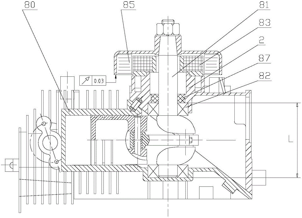
Figure 1 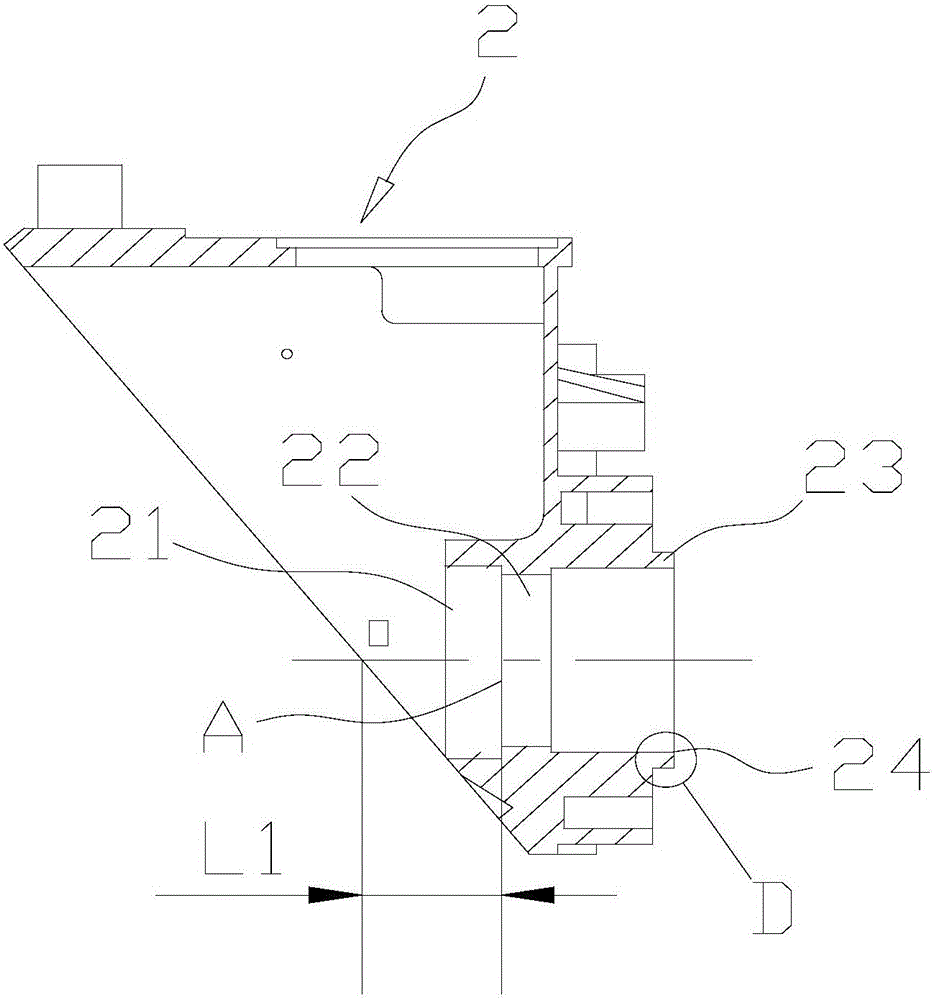
Figure 2 
Figure 3
Abstract
Description
technical field
[0001] The invention relates to a numerical control machining process of parts, in particular to a numerical control machining process of a bearing hole of a wedge-shaped crankcase cover. Background technique
[0002] like figure 1 It shows the partial structure diagram of the KG series digital generator set produced by a company. 80 is the generator body, 2 is the wedge-shaped crankcase cover, the body 80 and the wedge-shaped crankcase cover 2 are positioned by the combination of the inclined plane and the positioning pin and are connected by bolts as a whole; the two bearings 82 on the crankshaft 81 are respectively installed in the body 80 and the box. In the bearing hole of cover 2; 83, 85, 87 are the stator, rotor and oil seal of the generator set, respectively. The non-axiality of the rotor 85 is not more than 0.02mm, and the magnetic gap is 0.12mm.
[0003] In the schematic structural diagram, the dimensional accuracy of the distance L between the e...
Examples
Embodiment Construction
[0032] Below, in conjunction with accompanying drawing and specific embodiment, the present invention is further described:
[0033] see Figure 1 to Figure 5 , the present invention is a wedge-shaped crankcase cover bearing hole coefficient control processing technology, including the following steps:
[0034] Step 1. Design and manufacture a positioning fixture, and install the positioning fixture 1 on the spindle of the CNC lathe, so that the central axis of rotation of the positioning fixture 1 coincides with the axis of the main shaft of the lathe; fix the wedge-shaped crankcase cover 2 on the positioning fixture 1, so that the wedge-shaped crankshaft The common axis of the bearing hole system on the box cover 2 coincides with the axis of the lathe spindle, so that the lathe spindle, the rotation center axis of the positioning fixture 1 and the common axis of the bearing hole system of the wedge-shaped crankcase cover 2 can be coaxial; The main body of the positioning fi...