
Underground tunnel punching apparatus
A drilling device and tunnel technology, applied in drilling/drilling equipment, portable drilling rigs, metal processing equipment, etc., can solve the problems of inconvenience, waste of manpower, high labor intensity, etc., and achieve a small working angle range and easy operation. , the effect of avoiding errors
Patent Information
- Authority / Receiving Office
- CN · China
- Current Assignee / Owner
- Publication Date
- 2015-12-02
- Estimated Expiration
- Not applicable · inactive patent
Smart Images
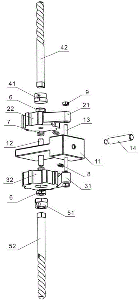
Figure 1 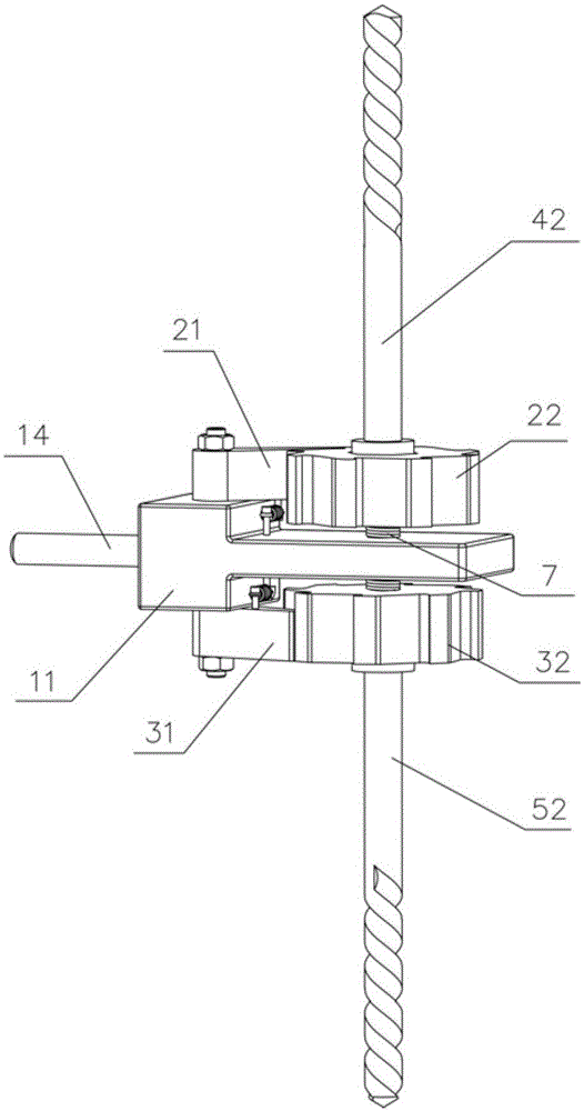
Figure 2 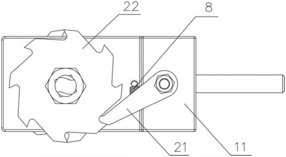
Figure 3
Abstract
Description
technical field
[0001] The invention belongs to the technical field of drilling devices, in particular to an underground tunnel drilling device. Background technique
[0002] In clay rocks, bauxite clay rocks and other earthy coal seam mines or underground tunnels with low mechanical strength, a large number of positioning holes are required in the continuous laying and maintenance of narrow-gauge lines under the tunnels to facilitate the installation of support columns in the continuously excavated tunnels , the existing narrow-gauge line punching mainly depends on gas cutting or hydraulic punching machine. Due to the existence of fire sources when using gas cutting, a full-time tile inspector must go to the site to check the gas concentration in detail before gas cutting. Gas explosions are likely to occur if the gas exceeds the limit, so gas cutting is absolutely prohibited in high gas locations; the hydraulic punching machine weighs about 150kg , heavy weight, unchanged...
Examples
Embodiment Construction
[0020] The present invention will be further described below in conjunction with accompanying drawing and specific embodiment:
[0021] Such as Figure 1 to Figure 4 As shown, the underground tunnel drilling device of the present invention includes a handle assembly, an upper ratchet structure, a lower ratchet structure, an upper drill bit assembly and a lower drill bit assembly, and the handle assembly includes a handle 11, a stud 12, a stud 13 and a handle handle 14 , the middle section of the stud bolt 12 and the middle section of the stud 13 are all pierced through the handle 11, and the handle 14 is arranged on the side of the handle 11; the upper ratchet structure and the lower ratchet structure are respectively arranged at the upper and lower ends of the handle 11, and the upper ratchet structure It includes an upper ratchet 21 and an upper ratchet 22 that cooperate with each other. The lower ratchet structure includes a lower ratchet 31 and a lower ratchet 32 that co...