
Swing knuckle arm head
A technology of swing arm and horn arm, which is applied in the field of swing arm head, which can solve the problems of no swing function and limited efficiency of window cleaning
Patent Information
- Authority / Receiving Office
- CN · China
- Patent Type
- Applications(China)
- Current Assignee / Owner
- Publication Date
- 2015-12-16
Smart Images
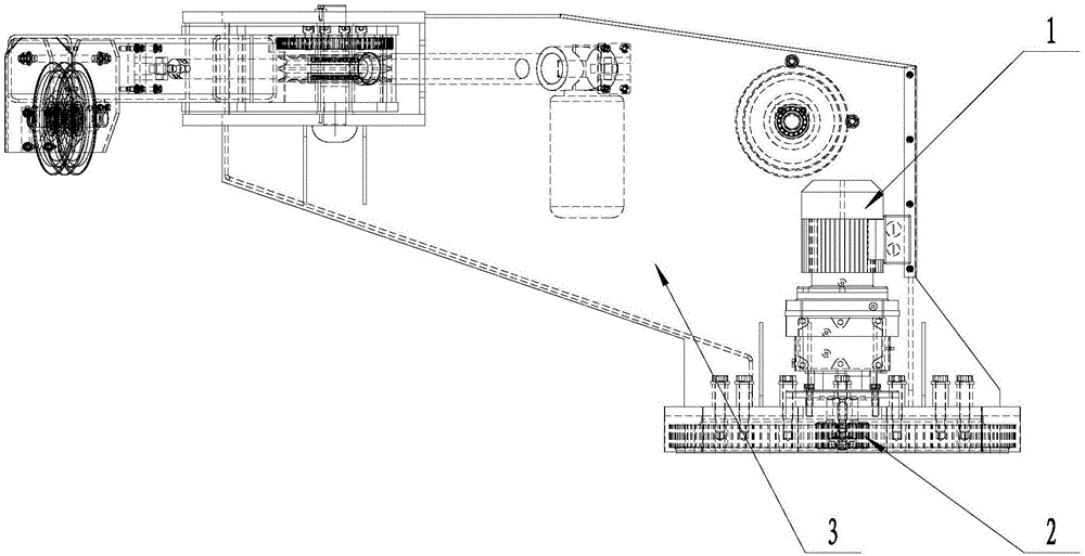
Figure 1 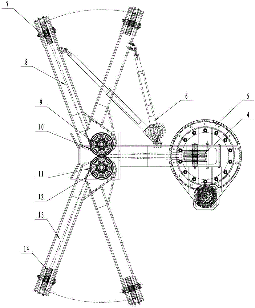
Figure 2 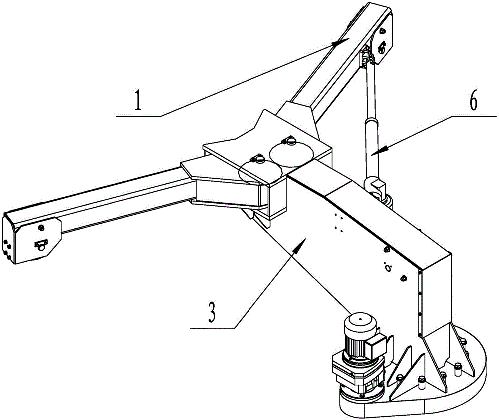
Figure 3
Abstract
Description
technical field
[0001] The invention belongs to components for window cleaners, in particular to a swinging horn arm head. Background technique
[0002] The claw arm head of the existing window cleaning machine is usually fixed, which can only rotate and has no swing function, which limits the working efficiency of window cleaning. Contents of the invention
[0003] The objective of the invention is to design a kind of swing claw arm head.
[0004] The present invention aims to solve the problem that the claw arm head of the existing window cleaning machine is usually fixed, can only rotate, and has no swing function, which limits the working efficiency of window cleaning.
[0005] In order to realize the purpose of the present invention, the technical solution adopted by the present invention is: a swinging horn arm head, comprising a slewing support, the slewing support is provided with a slewing chassis, a slewing gear and a slewing motor, and the slewing gear Connect...
Examples
Embodiment Construction
[0011] The present invention will be further described below in conjunction with the accompanying drawings and specific embodiments.
[0012] As shown in the figure, the present invention includes a slewing support 5 on which a slewing chassis 3 , a slewing gear 2 and a slewing motor 1 are arranged, and the slewing gear 2 is connected to the slewing motor 1 . The front end of the slewing chassis 3 is provided with a first swing arm 8, a second swing arm 13, a first gear 10 and a second gear 11, and the first gear 10 is arranged at the tail end of the first swing arm 8, so The above-mentioned second gear 11 is arranged at the tail end of the second swing arm 13 . The first gear 10 and the second gear 11 mesh with each other. An electric push rod 6 is connected to the arm body of the first swing arm 8 , and the other end of the electric push rod 6 is connected to the frame body of the rotary chassis 3 .
[0013] The first swing arm 8 and the second swing arm 13 are respectivel...