
An insulator and a method for improving the electric strength along the surface of the insulator
An insulator and surface area technology, which is used in the field of insulators and improving the electrical strength along the surface of insulators, can solve problems such as outstanding insulation problems, and achieve the effects of improved electrical resistance, low manufacturing technical difficulty, and easy processing.
Patent Information
- Authority / Receiving Office
- CN · China
- Patent Type
- Patents(China)
- Current Assignee / Owner
- Publication Date
- 2017-04-26
Smart Images
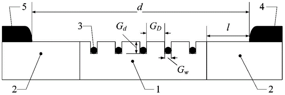
Figure 1 
Figure 2 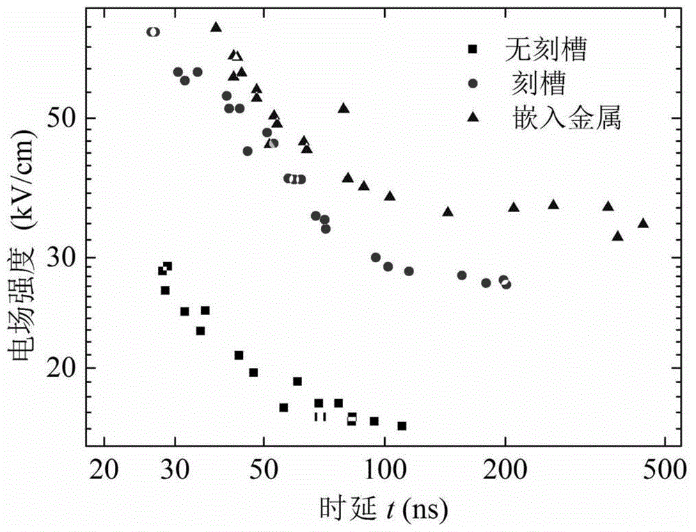
Figure 3
Abstract
Description
Technical field
[0001] The invention belongs to the technical field of insulators, and particularly relates to an insulator and a method for improving the electric strength along the surface of the insulator. Background technique
[0002] The insulator will break down along the surface when the breakdown strength is much lower than itself and the vacuum gap of the same size. For example, the critical breakdown of vacuum is about 350kV / cm, high-purity alumina ceramics is about 300~400kV / cm, and vacuum Alumina ceramic systems usually flashover under an electric field of tens of kV / cm, which seriously restricts the insulation performance of high-voltage vacuum electrical systems. Compared with conventional electric vacuum equipment, due to the limitation of volume and the requirement of compactness, the insulation problem of pulse power device is particularly prominent. Improving the creeping strength of insulators has become an unavoidable problem in the development of large-scale...
Examples
Embodiment 1
[0036] The groove area of the insulator is close to the cathode, the distance between the groove area and the cathode immediately l =0, the time delay characteristics of the surface flashover of the grooved insulator embedded in the electrode are as image 3 Shown. It can be seen from the figure that the flashover time delay after grooves on the surface of the insulator is greatly increased compared with that without grooves; when the electrodes are embedded in the grooves, the flashover time delay further increases. Table 1 shows the electric field intensity corresponding to different flashover time delays when the surface of the insulator has no groove, the groove near the cathode area, and the electrode is embedded in the groove. When the flashover time delay is 50ns, the flashover field strength of the groove on the surface is 43.4kV / cm, and the flashover field strength of the electrode embedded in the groove is 52.2kV / cm, and the electrode embedded in the groove is compar...
Embodiment 2
[0040] The groove position of the insulator is located in the middle area of the electrode, the distance between the groove area and the cathode l =5mm, Table 2 shows the electric field intensity corresponding to different flashover delays in the three cases of no grooves on the surface of the insulator, grooves near the cathode area, and electrodes embedded in the grooves. When the flashover time delay is 50ns, the flashover field strength of the groove on the surface is 26.7kV / cm, while the flashover field strength of the electrode embedded in the groove is 41.0kV / cm, and the electrode embedded in the groove is compared with that of the groove. The flashover field strength is increased by 53.5%; when the flashover time delay is 100ns, the flashover field strength of the groove on the surface is 22.3kV / cm, while the flashover field strength of the electrode embedded in the groove is 29.8kV / cm, while The flashover field strength of the embedded electrode is increased by 33.6% ...
Embodiment 3
[0044] The groove position of the insulator is close to the anode, the distance between the groove area and the cathode immediately l =10mm, Table 3 shows the electric field intensity corresponding to different flashover time delays in the three cases of no grooves on the surface of the insulator, grooves near the cathode area, and electrodes embedded in the grooves. When the flashover time delay is 50ns, the flashover field strength of the groove on the surface is 41.9kV / cm, and the flashover field strength of the electrode embedded in the groove is 57.4kV / cm, and the electrode embedded in the groove is compared with that of the groove. The flashover field strength is increased by 37.0%; when the flashover time delay is 100ns, the flashover field strength of the groove on the surface is 30.1kV / cm, while the flashover field strength of the electrode embedded in the groove is 39.0kV / cm, and the groove The flashover field strength of the embedded electrode is increased by 29.6% co...