
Frequency conversion measurement circuit for over-excitation protection and over-excitation protection method
A technology of overexcitation protection and measurement circuit, which is applied to the magnetic measurement environment, magnetic variable measurement, and measurement devices, etc. It can solve problems such as slow calculation speed, error in frequency measurement, and long inherent delay, so as to meet the requirements of operating time and Requirements for return time, prevention of accuracy errors, and the effect of inherently short delay
Patent Information
- Authority / Receiving Office
- CN · China
- Patent Type
- Patents(China)
- Current Assignee / Owner
- Publication Date
- 2018-09-21
Smart Images
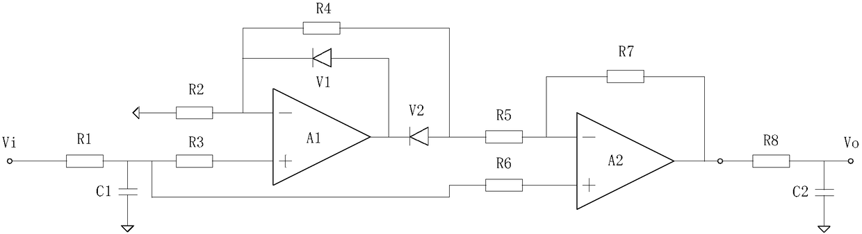
Figure 1 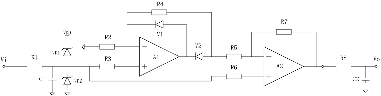
Figure 2 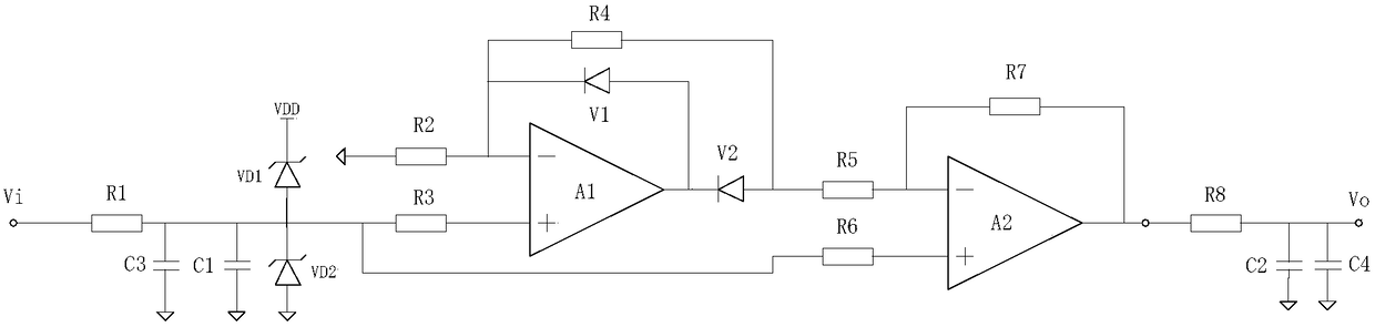
Figure 3
Abstract
Description
technical field
[0001] The invention relates to a frequency conversion measurement circuit for over-excitation protection and an over-excitation protection method, belonging to the technical field of relay protection for main equipment in a power system. Background technique
[0002] In the protection of large and medium-sized generators or transformers in power systems, the inverse time overexcitation protection is a must-have protection to prevent overheating of the iron core caused by overexcitation. Conventional inverse time overexcitation protection usually uses software calculation method to realize the measurement of overexcitation multiple, which is generally realized by the following method: introduce voltage through voltage transformer, sample voltage signal to obtain instantaneous voltage value, and digitally calculate voltage U value and frequency respectively Measure the f value, and then synthesize and calculate the U / f value; or measure the zero-crossing point...
Examples
Embodiment Construction
[0045] The present invention will be further described below in conjunction with the accompanying drawings. The following examples are only used to illustrate the technical solution of the present invention more clearly, but not to limit the protection scope of the present invention.
[0046] Such as figure 1 As shown, the frequency conversion measurement circuit for overexcitation protection provided by the present invention includes power supply VDD, ground GND, operational amplifier A1, operational amplifier A2, diode V1, diode V2, sampling resistor R1, sampling capacitor C1, resistor R2, Resistor R3, resistor R4, resistor R5, resistor R6, resistor R7, filter resistor R8 and filter capacitor C2; the signal to be measured Vi is connected to one end of the sampling resistor R1, and the other end of R1 is grounded to GND through the sampling capacitor C1 and connected to the resistor R3 To the positive input terminal of the operational amplifier A1, connected to the positive ...