
High-efficiency control method of inverter fractional voltage and frequency in microgrid off-grid mode
A control method and fractional-order technology, applied in the direction of converting AC power input to DC power output, electrical components, single-grid parallel feeding arrangement, etc. Guarantee optimal operation and other issues
Patent Information
- Authority / Receiving Office
- CN · China
- Patent Type
- Patents(China)
- Current Assignee / Owner
- Publication Date
- 2018-09-18
Smart Images
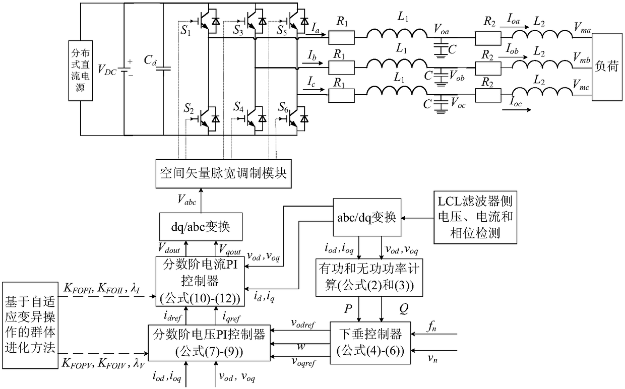
Figure 1 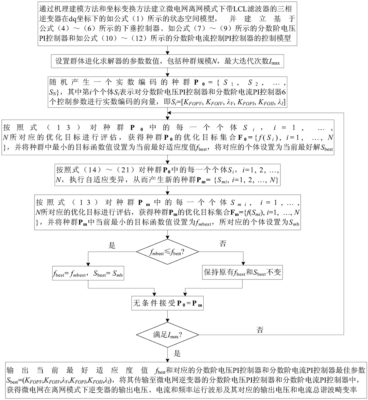
Figure 2 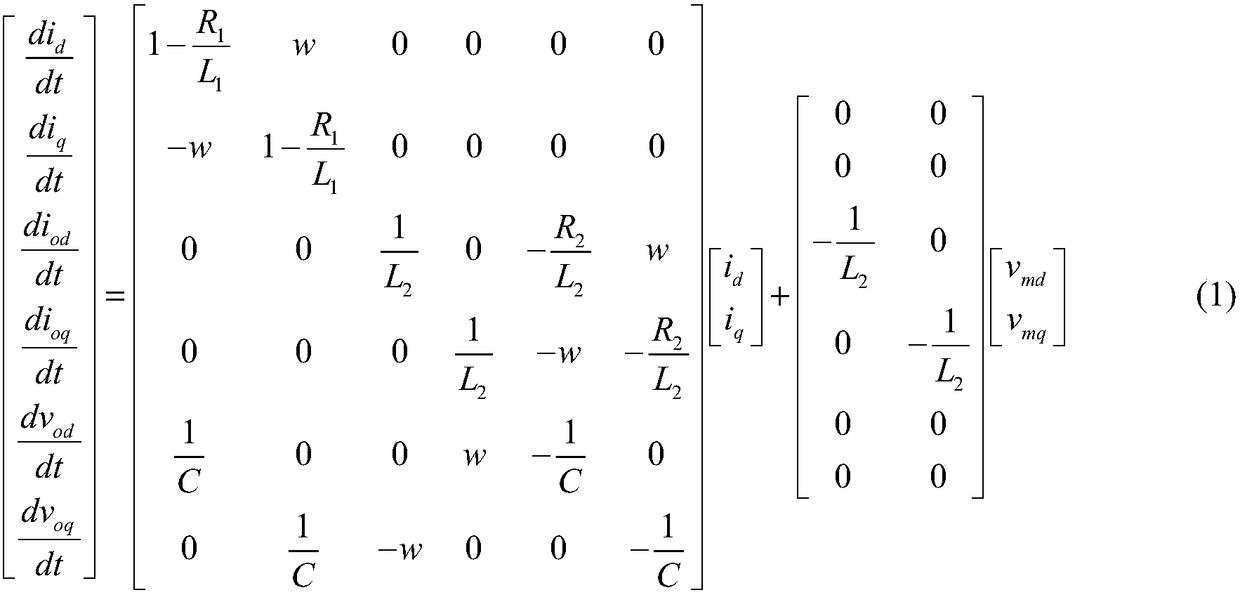
Figure 3
Abstract
Description
technical field
[0001] The invention relates to an intelligent control technology in the field of microgrid power electronics technology, in particular to an efficient control method for fractional-order voltage and frequency of an inverter in a microgrid off-grid mode. Background technique
[0002] As an important form of efficient application of new energy distributed power, microgrid can promote the large-scale access of renewable energy, and is expected to realize the highly reliable supply of various energy forms for loads. It is widely regarded as a kind of active distribution network Therefore, microgrids have received extensive attention and research and development in recent years. Among them, how to realize the efficient control and energy optimization management of the inverter in the microgrid’s off-grid mode has become one of the research and development hotspots in the field of microgrid technology, and how to design the inverter voltage and frequency in the of...
Examples
Embodiment Construction
[0043] The present invention will be further described below in conjunction with the accompanying drawings, and the purpose and effect of the present invention will be more obvious.
[0044] figure 1 It is a schematic diagram of the principle of the fractional-order voltage and frequency efficient control method of the inverter in the off-grid mode of the microgrid. Among them, V DC Indicates the DC voltage on the side of the distributed DC power supply, C d Indicates the capacitance of the distributed DC generator side, L 1 and L 2 Respectively represent the inductance values of the first and second inductors of the LCL filter, C represents the LCL filter capacitor, R 1 and R 2 Respectively represent the filter inductance L 1 and L 2 Corresponding equivalent resistance value, V oa , V ob , V oc Respectively represent the three-phase voltage of the filter capacitor in the LCL filter, V ma , V mb , V mc respectively represent the three-phase voltages on the load ...