
A Derrick Defect Inspection Robot
A technology for inspection robots and defects, which is applied in manipulators, program-controlled manipulators, manufacturing tools, etc., and can solve problems such as large data errors, potential safety hazards, and rough detection.
Patent Information
- Authority / Receiving Office
- CN · China
- Patent Type
- Patents(China)
- Current Assignee / Owner
- Publication Date
- 2018-12-07
- Estimated Expiration
- Not applicable · inactive patent
Smart Images
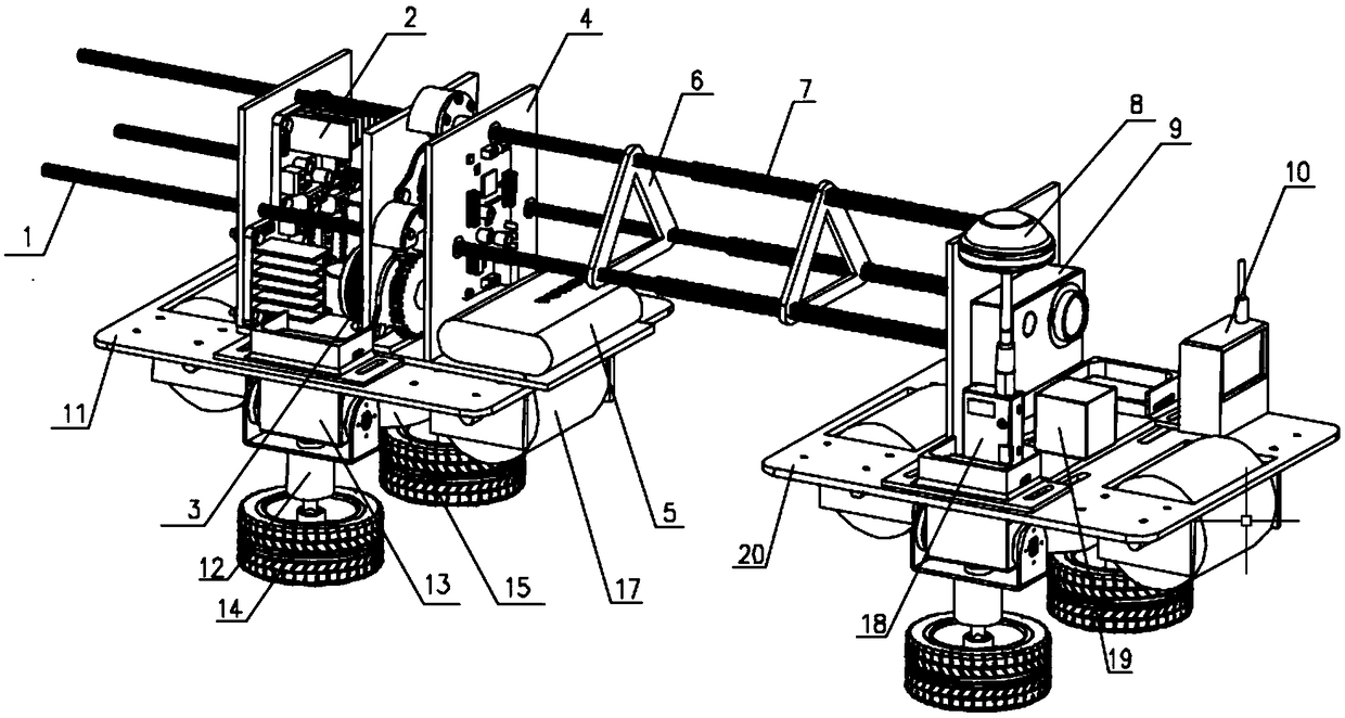
Figure 1 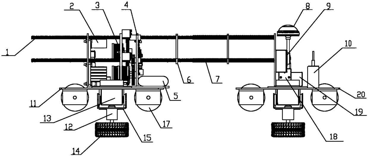
Figure 2 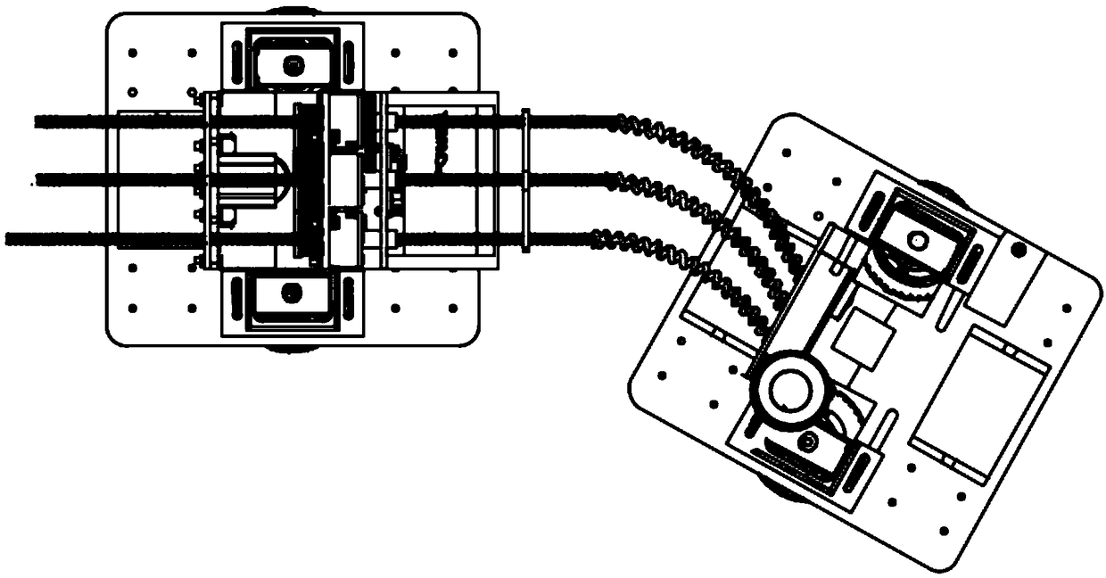
Figure 3
Abstract
Description
technical field
[0001] The invention relates to a derrick inspection device, in particular to a derrick defect inspection robot. Background technique
[0002] The derrick is an important part of lifting equipment such as metallurgical mining, coal mining, and oil drilling. In the actual work of the derrick, under the influence of various factors such as working lifting load and fluctuating wind load, the derrick produces three-dimensional swing deformation in the plane and elevation directions. When the deformation exceeds a certain limit, it will seriously affect the safety of production and become the most dangerous safety hazard in the working process. For this reason, the dynamic deformation of the derrick must be mastered in order to take corresponding safety precautions. From top to bottom, the base strata of the derrick bracing are filled soil, loess-like silty clay, clay and residual soil. The material composition of this layer is complex, without the necessary co...
Examples
Embodiment Construction
[0024] The present invention will be further described below.
[0025] Such as Figure 1 to Figure 5 Shown, the present invention comprises front car, connecting structure and rear car, and front car is connected with rear car by connecting structure;
[0026]Described front car comprises front vehicle frame 20, antenna, signal transmitter 18, signal receiver 10, motion camera 9, electromagnet 15, front clamping drive mechanism and triaxial acceleration sensor 19, described signal transmitter 18, signal The receiver 10, the motion camera 9 and the triaxial acceleration sensor 19 are arranged on the front frame 20, and the antenna is arranged on the top of the signal transmitter 18; the bottom of the front frame 20 is provided with two groups of rollers 17, and the rollers 17 pass It is hinged with the front frame 20; the front clamping drive mechanism is arranged at the bottom of the front frame 20, and the front clamping drive mechanism is composed of two steering gears 13, ...