
End surface air inlet device for rotor engine
A technology of rotary engine and air intake device, applied in combustion engine, machine/engine, internal combustion piston engine, etc., can solve the problems of sharp turn of end-face intake air flow, small inflation coefficient and average effective pressure, large fluid resistance, etc. The effect of improving the inflatable coefficient, good inflatable coefficient, and improving the inflatable coefficient
Patent Information
- Authority / Receiving Office
- CN · China
- Patent Type
- Applications(China)
- Current Assignee / Owner
- Publication Date
- 2017-05-10
Smart Images
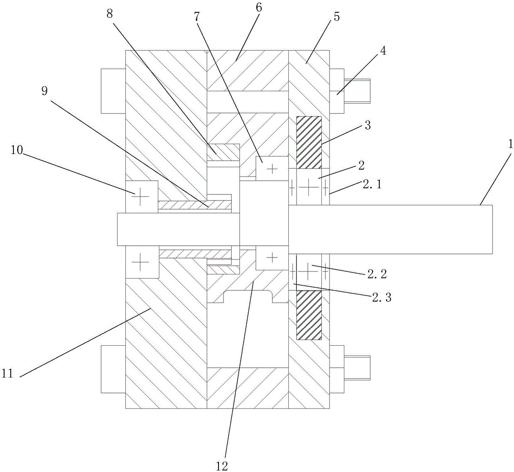
Figure 1 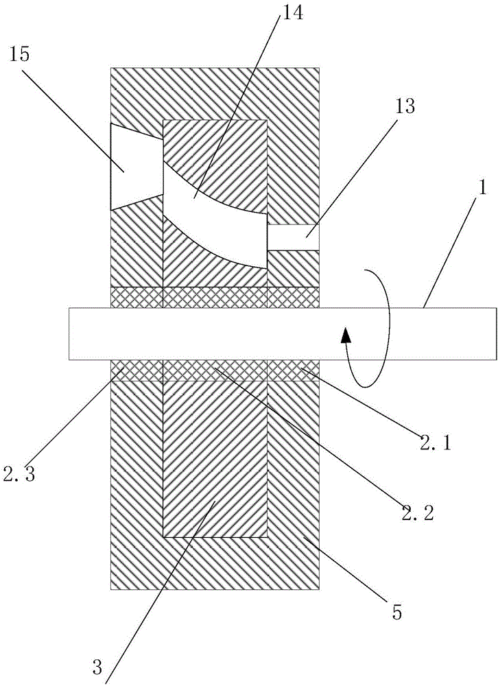
Figure 2 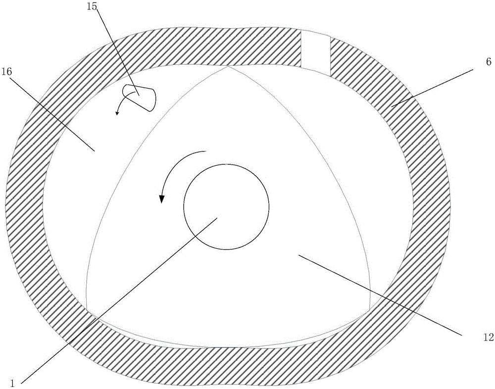
Figure 3
Abstract
Description
technical field
[0001] The invention relates to auxiliary equipment for a micro-rotary engine, in particular to an end face air intake device for a rotary engine, which belongs to the field of engines. Background technique
[0002] With the development of micro-electro-mechanical systems (MEMS) and the introduction of a variety of miniaturized military equipment concepts, the development of micro-energy systems with small volume, light weight, high energy density, and continuous operation has become the focus of attention of various countries. Compared with conventional portable power sources, micro-engines use hydrocarbons as fuels, which have much higher energy density, stable voltage, and low cost. Therefore, micro-engines will have wide application prospects in electronic devices in various industries such as industry, agriculture, environmental protection, medical and health care, etc., and can also directly provide power for micro-machines such as micro-cars, micro-pla...
Examples
Embodiment 1
[0029] Such as figure 1 , 2 As shown, the end face air intake device for a rotary engine disclosed in this embodiment includes a crankshaft 1, a bearing 2, a first rotor 3, a bolt 4, a front end cover shell 5, a cylinder 6, a fourth bearing 7, an internal gear 8. External gear 9, fifth bearing 10, rear end cover 11, second rotor 12, first air intake 13, second air intake 14, third air intake 15 and combustion chamber 16. The front end cover includes a front end cover shell 5 and a first rotor 3, the first rotor 3 is placed in the front end cover shell 5, and the left and right sides of the front end cover shell 5 are respectively opened with a third air inlet 15 and a first air inlet 13 , the first rotor 3 has a second air inlet 14; the bearing 2 includes a first bearing 2.1, a second bearing 2.2 and a third bearing 2.3; the first bearing 2.1 cooperates with the first rotor 3, and the second bearing 2.2 , The third bearing 2.3 cooperates with the front end cover shell 5 on t...